LIFEPAK 15 Monitor/Defibrillator
Service Manual
Replacement Procedures
Power/Contact PCB Cable (W05) Replacement
Section Menu Section Contents Procedures Back Index
326
8
Power/Contact PCB Cable (W05) Replacement
Power/contact PCB cable replacement consists of the following procedures:
• Removing the Power/Contact PCB Cable (W05) (p. 326)
• Installing the Power/Contact PCB Cable (W05) (p. 327)
Removing the Power/Contact PCB Cable (W05)
To remove the power/contact PCB cable (3207261-001) from the rear
case:
1. Disassemble the case as described in Disassembling the Case (p.
181).
2. Remove the system/therapy PCB assembly as described in System
(A01)/Therapy (A04) PCB Assembly Replacement (p. 232).
3. Disconnect the power/contact PCB cable from the power PCB at
J12 (may be labeled P12).
4. Remove the transfer relay as described in Removing the Transfer
Relay Assembly (A13) (p. 269).
NOTE: It is not necessary to remove the spade terminals as
described in the procedure.
5. Remove the OEM PCB as described in Removing the OEM PCB
(A06) (p. 262).
6. Remove the NIBP/CO2 assembly as described in Removing the
NIBP (A21)/CO2 (A23) Modules (p. 288).
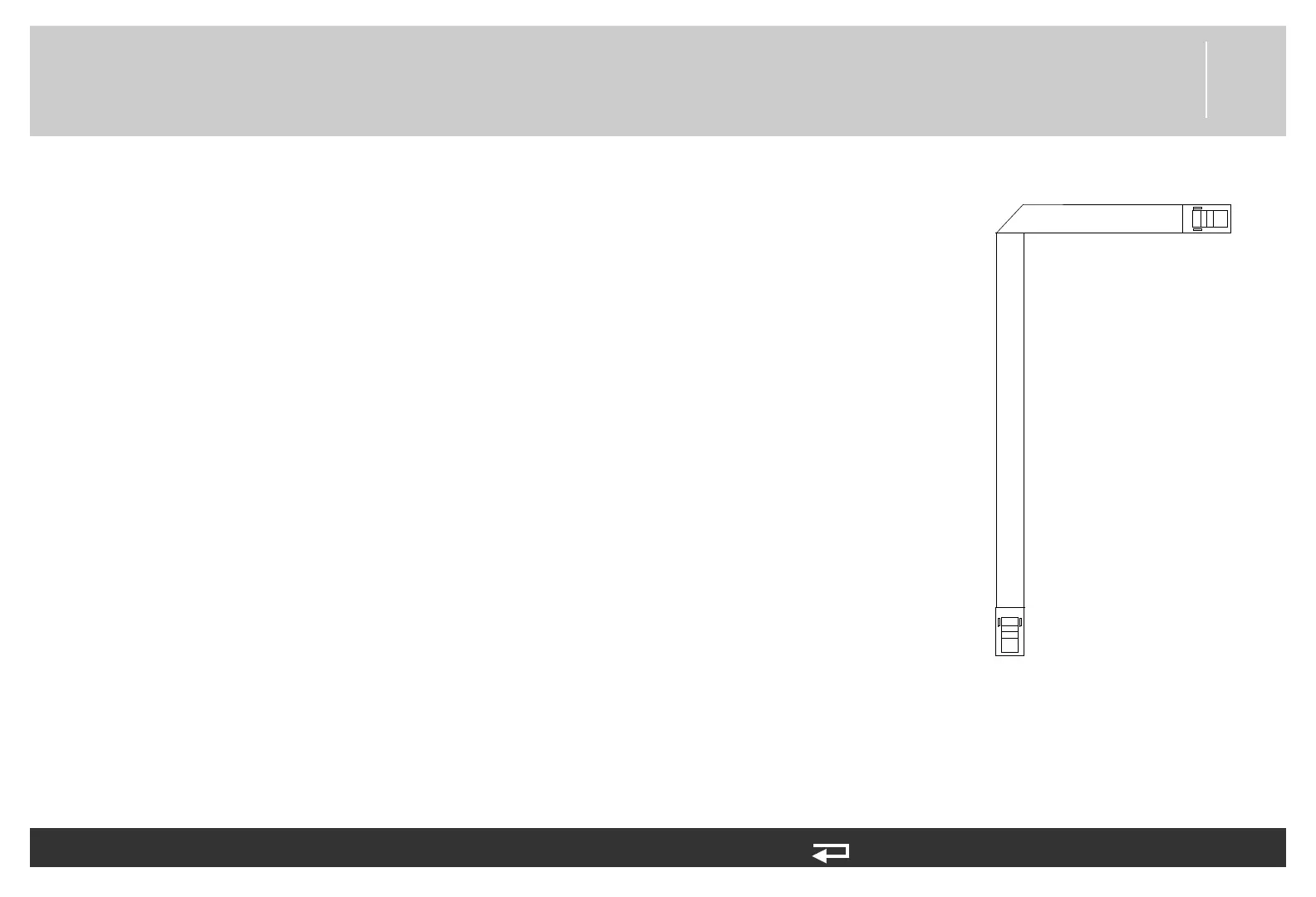
7. Disconnect the power/contact PCB cable at J42 of the contact PCB (A07).
8. Remove the power/contact cable.
P42
P12
Power PCB (A03)
A07
Contact PCB
Figure 8.107—Power/contact PCB
cable connections