LIFEPAK 15 Monitor/Defibrillator
Service Manual
Replacement Procedures
Contact PCB (A07) Replacement
Section Menu Section Contents Back Index
359
8
Contact PCB (A07) Replacement
Contact PCB replacement consists of the following procedures:
• Removing the Contact PCB (A07) (p. 359)
• Installing the Contact PCB (A07) (p. 359)
Removing the Contact PCB (A07)
To remove the contact PCB (3207037-002) (from outside the rear case) (see
Figure 9.14 on p. 400):
1. Lay the device face down on a static-free, non-abrasive surface.
2. Remove the two screws (201407-069) from the battery retainer
(3207881-000) between the battery wells. Lift away the battery
retainer. Discard the screws.
3. Lift the Contact PCB away for rear case far enough to access and
disconnect the power/contact PCB cable (3207261-001) (W05) at
J42.
Installing the Contact PCB (A07)
To install the contact PCB (3207037-002) on the outside of the rear case:
1. Lay the device face down on a static-free, non-abrasive surface.
2. Connect the contact PCB to the power/contact PCB cable (W05) at J42.
3. Install the contact PCB by sliding the assembly straight down tracks in rear case.
4. Install the two new screws (201407-069) into the battery retainer (3207881-000) between the battery wells; torque to
10.0 in-lb using P2 bit.
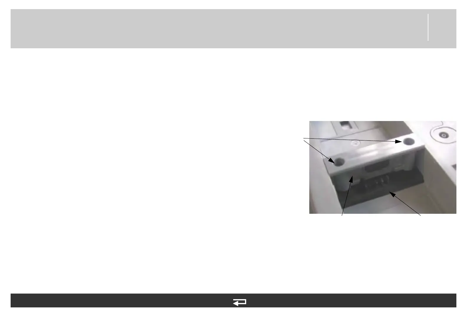
contact
PCB
battery
retainer
screws
Figure 8.122—Contact PCB screw and part locations