LIFEPAK 15 Monitor/Defibrillator
Service Manual
Replacement Procedures
Printer Assembly/Interface PCB Cable (W16) Replacement
Section Menu Section Contents Procedures Back Index
221
8
Printer Assembly/Interface PCB Cable (W16) Replacement
Refer to Inside Front Case Diagram (p. 189).
Removing the Printer Assembly/Interface PCB Cable (W16)
To remove the printer/interface PCB cable (3009724-001) (see Figure 9.56 on p. 478) from the
front case:
1. Disassemble the case as described in Disassembling the Case (p. 181).
2. Spread the connector locking tabs and eject the W16 cable from the A05 interface PCB at
J35.
3. Disconnect the W19 cable ground terminal from the printer assembly connector bracket.
4. Remove the retaining screw (3207337-312) and connector bracket (3006810-01) on the
A12 printer assembly housing that secures the W16 cable at P40. Discard the screw.
5. With a flat edged tool, gently pry the W16 cable at P40 out of the J40 connector on the
printer assembly. Remove and discard the rubber moisture gasket (3006809-00).
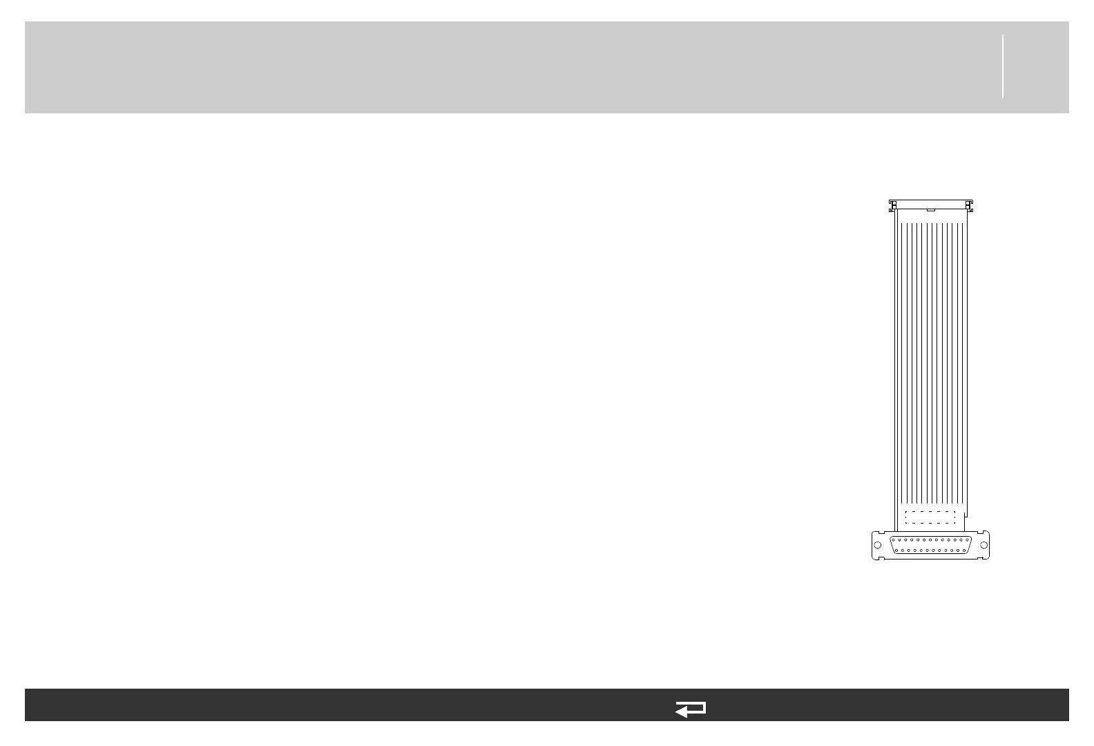
P40
P35
to A12 - J40
to A05 - J35
Figure 8.30—Printer / Interface
PCB connection