LIFEPAK 15 Monitor/Defibrillator
Service Manual
Replacement Procedures
System/Interface PCB Cable (W04) Replacement
Section Menu Section Contents Procedures Back Index
212
8
System/Interface PCB Cable (W04) Replacement
Refer to Inside Front Case Diagram (p. 189).
Removing the System/Interface PCB Cable (W04)
To remove the system/interface PCB W04 cable (3206991-003) (see Figure 8.11 on p.
191 and Figure 9.44 on p. 466) from the front case:
NOTE: Cable solder connections are fragile; keep handling to a minimum.
1. Disassemble the case as described in Disassembling the Case (p. 181). This
procedure removes the W04 cable from the system PCB (A01) at J2.
2. Disconnect the W04 cable from the interface PCB at J30.
Installing the System/Interface PCB Cable (W04)
To install the system/interface PCB W04 cable (3206991-003) (see Figure 9.44 on p.
466) into the front case:
1. Snap connector of the System/Interface cable (W04) (3206991-003) over tabs and
connect to interface PCB at J30. Check that connector is fully seated.
2. Reassemble the case as described in Reassembling the Case (p. 184) to connect
the W04 cable to the system PCB (A01) at J2.
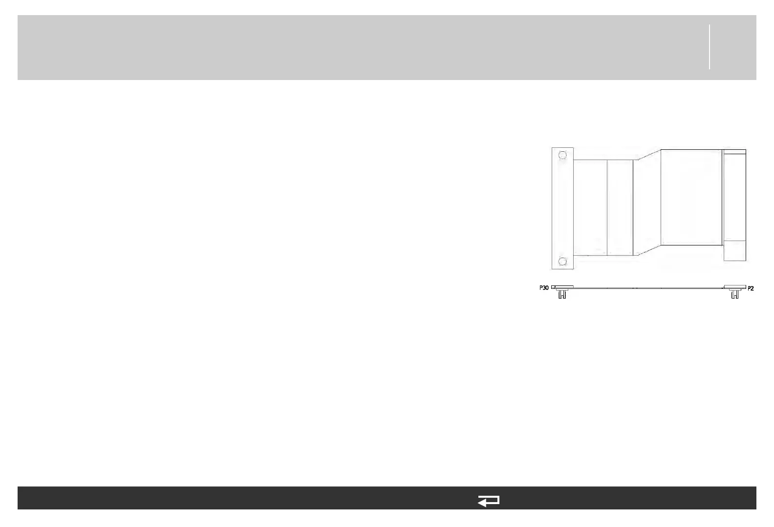
Figure 8.21—System/interface PCB
cable connections
to A05 - J30
to A01 - J2