LIFEPAK 15 Monitor/Defibrillator
Service Manual
Replacement Procedures
Power/System PCB Cable (W01) Replacement
Section Menu Section Contents Procedures Back Index
323
8
Power/System PCB Cable (W01) Replacement
Power/system PCB cable replacement consists of the following procedures:
• Removing the Power/System PCB Cable (W01) (p. 323)
• Installing the Power/System PCB Cable (W01) (p. 323)
Removing the Power/System PCB Cable (W01)
To remove the power/system PCB cable from the rear case (refer to Inside Rear Case Diagrams (p.
228)):
1. Disassemble the case as described in Disassembling the Case (p. 181).
2. Remove the system/therapy PCB assembly as described in System (A01)/Therapy (A04) PCB
Assembly Replacement (p. 232).
3. Remove the OEM shield (3208298-000).
4. For orientation, locate power PCB-J17 on the rear case diagram. (The system PCB J1 end of the
power/system PCB cable was disconnected as part of step 2.)
5. Press the connector locking tabs, and then disconnect the power/system PCB cable from the
power PCB (W03) at J17.
Installing the Power/System PCB Cable (W01)
To install the power/system PCB cable into the rear case (refer to Inside Rear Case Diagrams (p. 228)):
1. Connect the power/system PCB cable (3207692-000) to the power PCB (A03) at J17 (see Figure 8.58 on p. 260).
2. Install the OEM shield (3208298-000).
3. Install the system/therapy PCB assembly (described in System (A01)/Therapy (A04) PCB Assembly Replacement (p. 232)).
4. Reassemble the case as described in Reassembling the Case (p. 184).
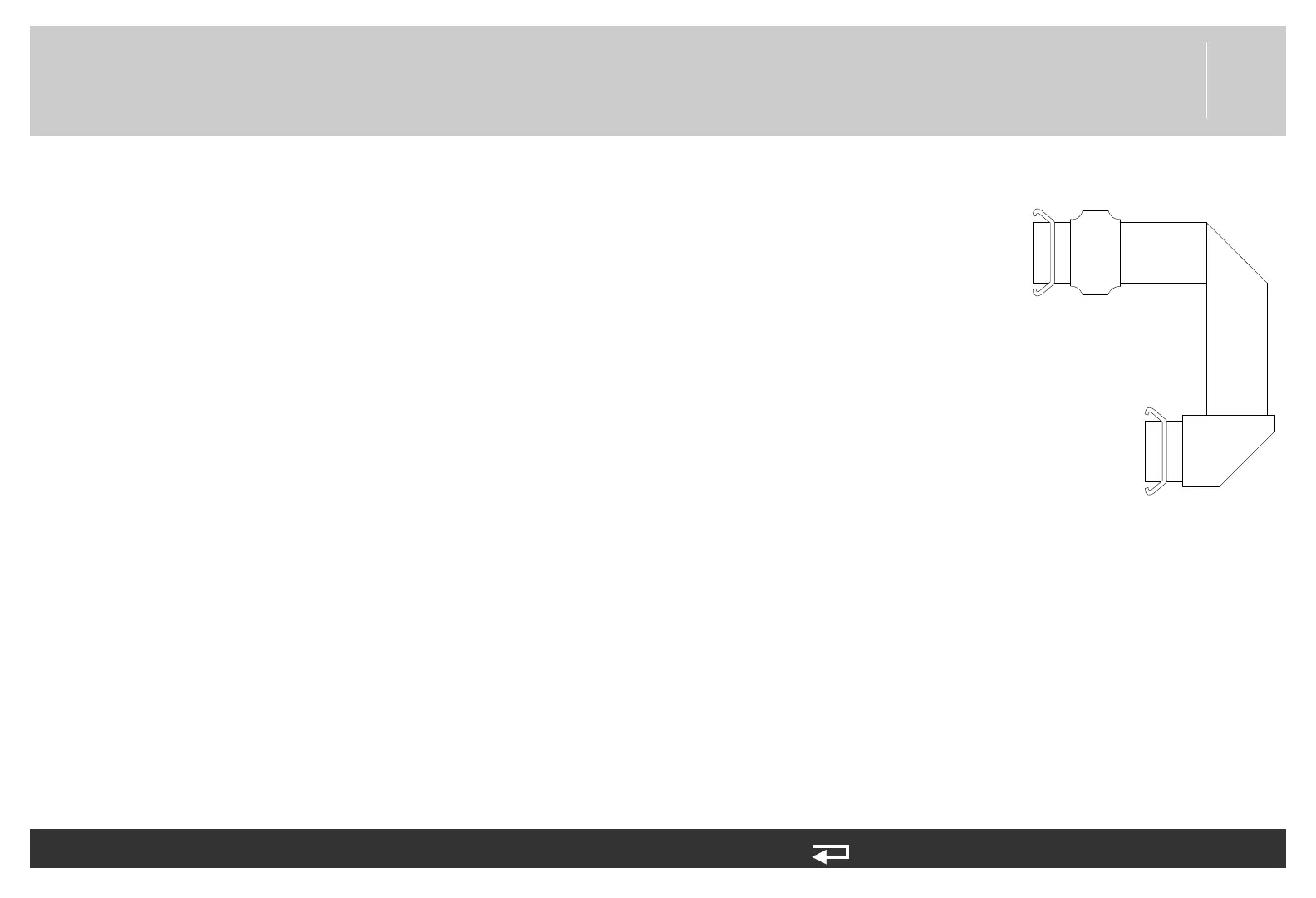
P01
P17
Power PCB (A03)
System PCB (A01)
Figure 8.105—Power/system
PCB cable connections