LIFEPAK 15 Monitor/Defibrillator
Service Manual
Assembly Diagrams and Parts Lists
Connection Diagrams for Assemblies, Control Boards, Cables, and
Connectors
Section Menu Section Contents
Back
Index
478
9
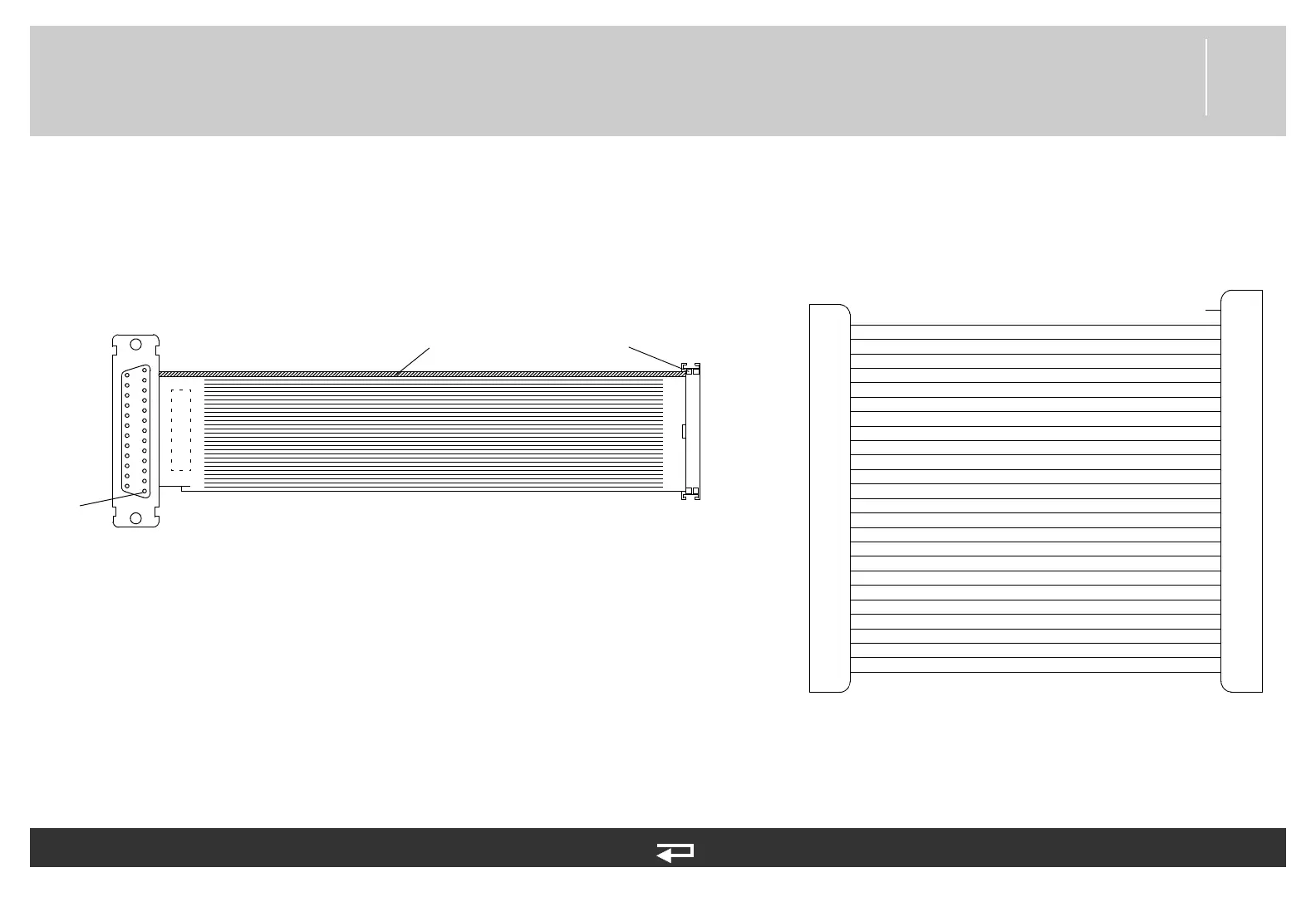
Printer Assembly/Interface PCB Cable
Figure 9.56—Diagram for item W16
P40
P35
Pin 1
far side
stripe
Pin 1
Interface PCB (p. 447)
Printer Assembly (p. 454)
1
14
2
15
3
16
4
17
5
18
6
19
7
20
8
21
9
22
10
23
11
24
12
25
13
26
25
24
23
22
21
20
19
18
17
16
15
14
13
12
11
10
9
8
7
6
5
4
3
2
1
NC
P40
Interface
PCB
printer
EMITTER
ANODE
HEAD TYPE
VHD
VDD
GND
GND
LATCH
MOTOR -
VHD
STB1*
MOTOR +
CHASSIS GND
THERM 1
CLK
DATA
VSS
GND
GND
STB2*
THERM 2
VHD
CATHODE
COLLECTOR
VHD
Refer to Figure 9.7: Front Case parts view 3 of 3, p. 380.
See MIN 3009724-001 in table for parts information.