LIFEPAK 15 Monitor/Defibrillator
Service Manual
Assembly Diagrams and Parts Lists
Connection Diagrams for Assemblies, Control Boards, Cables, and
Connectors
Section Menu Section Contents
Back
Index
447
9
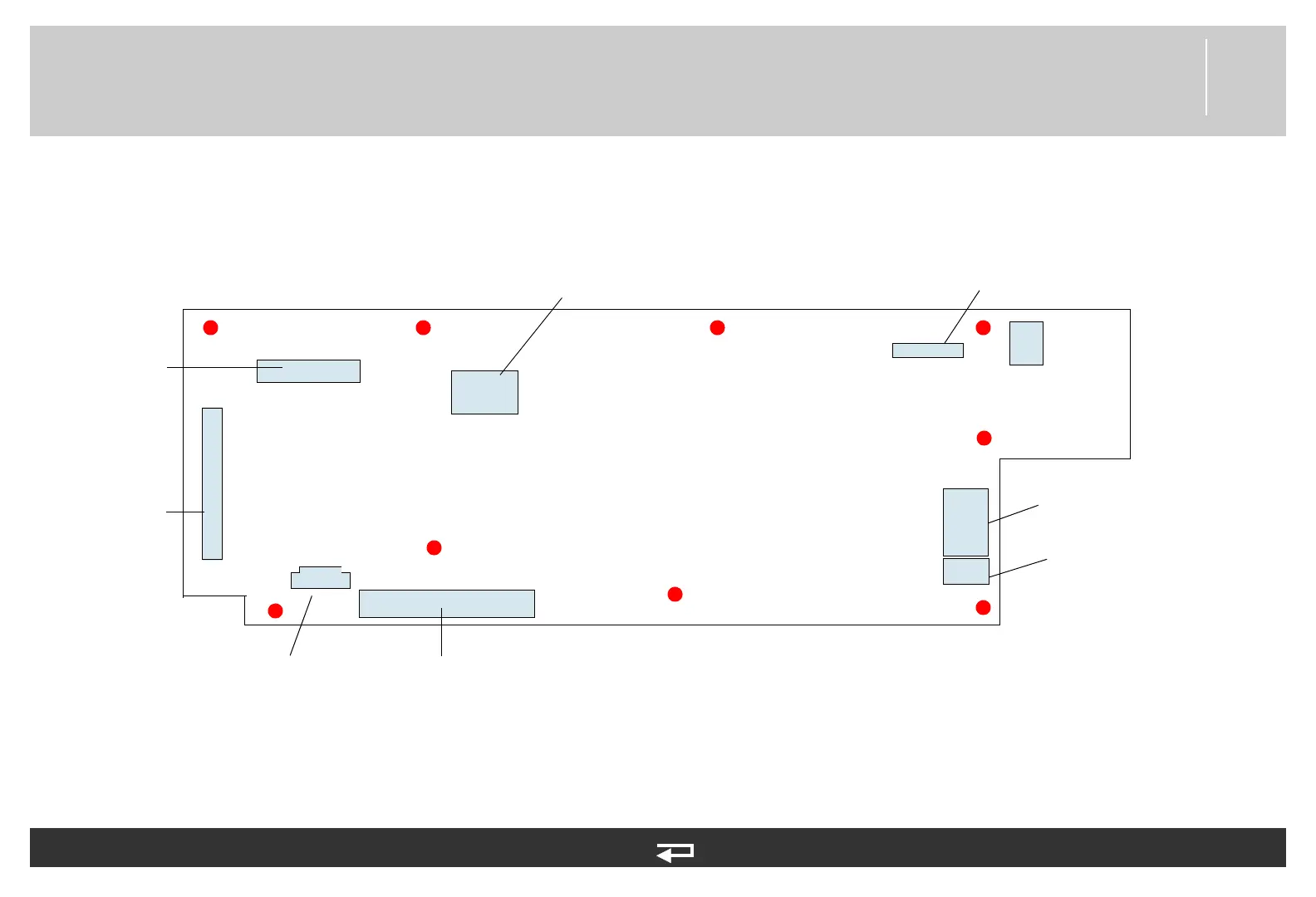
Interface PCB
Figure 9.25—Diagram for item A05
LCD Assembly/
Interface PCB
Cable (p. 480)
System PCB/
Interface PCB
Cable (p. 466)
Main Keypad/
Interface PCB
Cable (p. 475)
Speed Dial
Assembly (p. 477)
Printer Assembly/Interface
PCB Cable (p. 478)
Speaker Assembly
(p. 479)
Printer Control
Keypad/Interface
PCB Cable (p. 474)
Refer to Figure 9.6: Front Case parts view 2 of 3, p. 379.
See MIN 3206815 in table for parts information.
J30
J37
J35
J33
J34
J32
J36
J39
J31
Backlight PCB/
Interface PCB
Cable (p. 468)