LIFEPAK 15 Monitor/Defibrillator
Service Manual
Assembly Diagrams and Parts Lists
Connection Diagrams for Assemblies, Control Boards, Cables, and
Connectors
Section Menu Section Contents
Back
Index
446
9
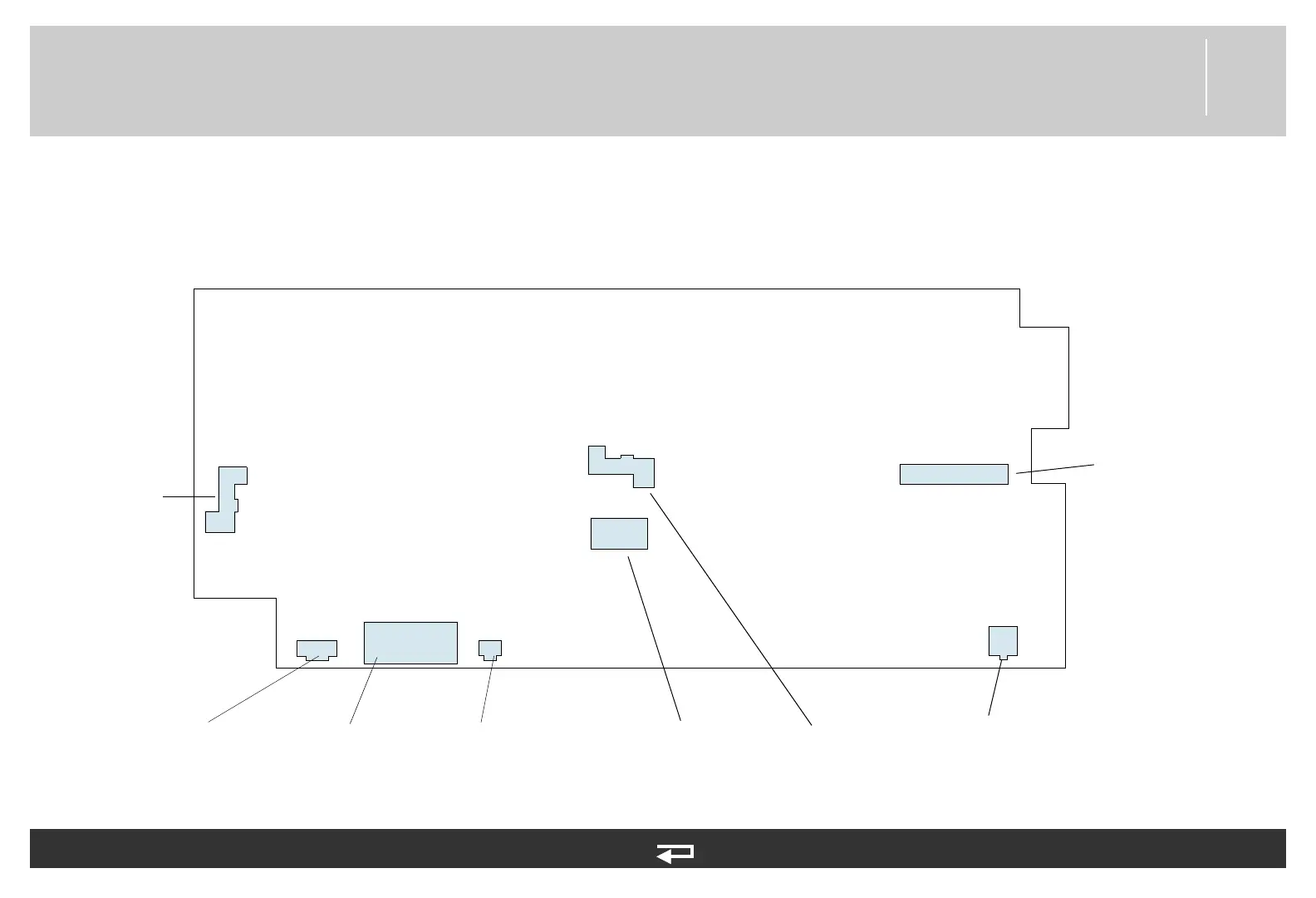
Therapy PCB
Figure 9.24—Diagram for item A04
System PCB/Therapy
PCB Connector (p. 465)
Power PCB/Therapy PCB
Cable (p. 464)
Transfer Relay
Assembly (p.
455)
Energy Storage
Capacitor (p.
457)
Transfer Relay
Assembly (p.
455)
Therapy
Connector Cable
(p. 473)
J51
J21
J18
J19
J50
J20
J22
Biphasic to Therapy
PCB Flex Cable (p.
482)
J23
Transfer Relay
Assembly (p. 455)
Refer to System/Therapy PCB Assembly Diagrams and Parts List (p. 387) and Figure 9.9: System/Therapy
PCB assembly view 2 of 2, p. 388
See also MIN 3306311 in table for parts information.