LIFEPAK 15 Monitor/Defibrillator
Service Manual
Assembly Diagrams and Parts Lists
Connection Diagrams for Assemblies, Control Boards, Cables, and
Connectors
Section Menu Section Contents
Back
Index
445
9
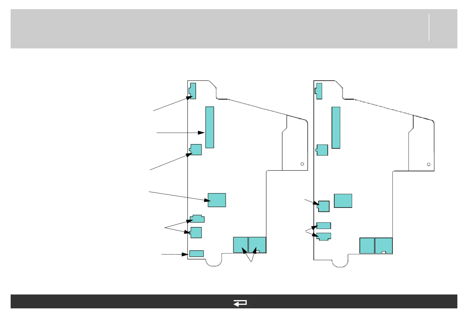
Power PCB
Figure 9.23—Diagram for item A03
J12
J08
J16
J13
J11
J15
J09
J10
Power PCB/Therapy
PCB Cable (p. 464)
System Connector
Cable (p. 470)
Battery Pins/Power
PCB Cable (p. 472)
OEM PCB Module
(p. 448)
Power PCB/System PCB
Cable (p. 463)
Power PCB/Contact PCB
Cable (p. 467)
Refer to Figure 9.17: Rear Case view 4 of 7, p.
403.
See MIN 3206749-003 in table for parts
information.
J17
J12
J08
J16
J15-A
J11
J15-B
J09
J10
J17
Battery Pins/
Power PCB
Cable (p. 472)
Auxiliary Power
Connector
Cable (V2) (p.
471)
Power PCB, V2
with Aux. Power
Aux Power
Cable (V1)