LIFEPAK 15 Monitor/Defibrillator
Service Manual
Assembly Diagrams and Parts Lists
Connection Diagrams for Assemblies, Control Boards, Cables, and
Connectors
Section Menu Section Contents
Back
Index
463
9
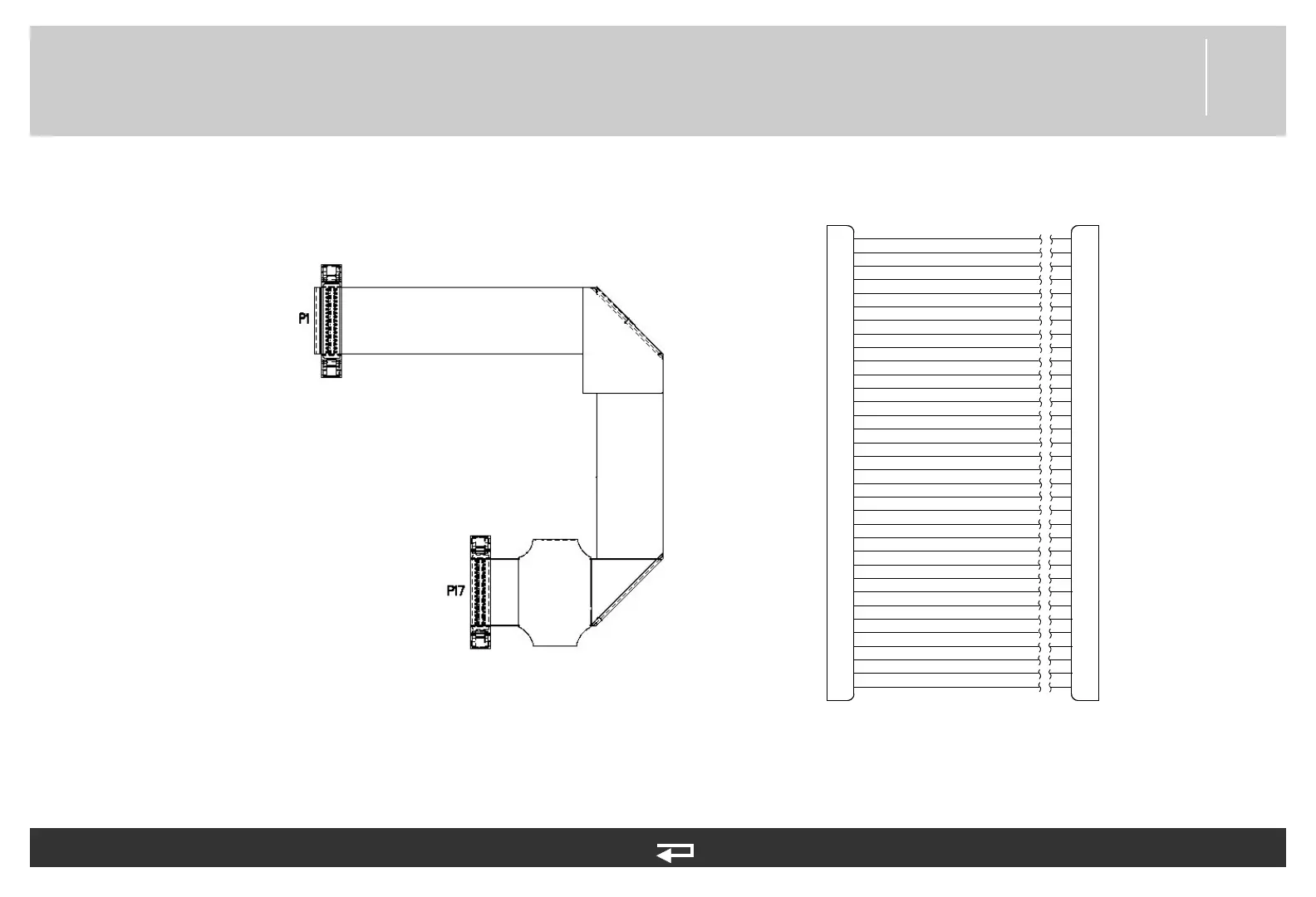
Power PCB/System PCB Cable
Figure 9.41—Diagram for item W01
System PCB (p. 444)
Power PCB (p. 445)
Refer to Figure 9.17: Rear Case view 4 of 7, p. 403.
See MIN 3207692-000 in table for parts information.
SYS RTS
1
2
3
4
5
6
7
8
9
10
11
12
13
14
15
16
17
18
19
20
21
22
23
24
25
26
27
28
29
30
31
32
33
34
34
33
32
31
30
29
28
27
26
25
24
23
22
21
20
19
18
17
16
15
14
13
12
11
10
9
8
7
6
5
4
3
2
1
P1
P17
PS FAIL*
PWR FAIL*
CHG LED
PWR LED
PWR MON
PWR SW*
GND
GND
OEM VPP ENA
ET RX
NIBP ON
ET TX
OEM RES*
SP TX
SP RX
NIBP RX
NIBP TX
GND
SYS RX
SYS TX
SYS CTS
SYS DTR
ANALOG ECG
GND
GND
SP ET SYNC
PWR RX
PWR TX