LIFEPAK 15 Monitor/Defibrillator
Service Manual
Assembly Diagrams and Parts Lists
Connection Diagrams for Assemblies, Control Boards, Cables, and
Connectors
Section Menu Section Contents
Back
Index
464
9
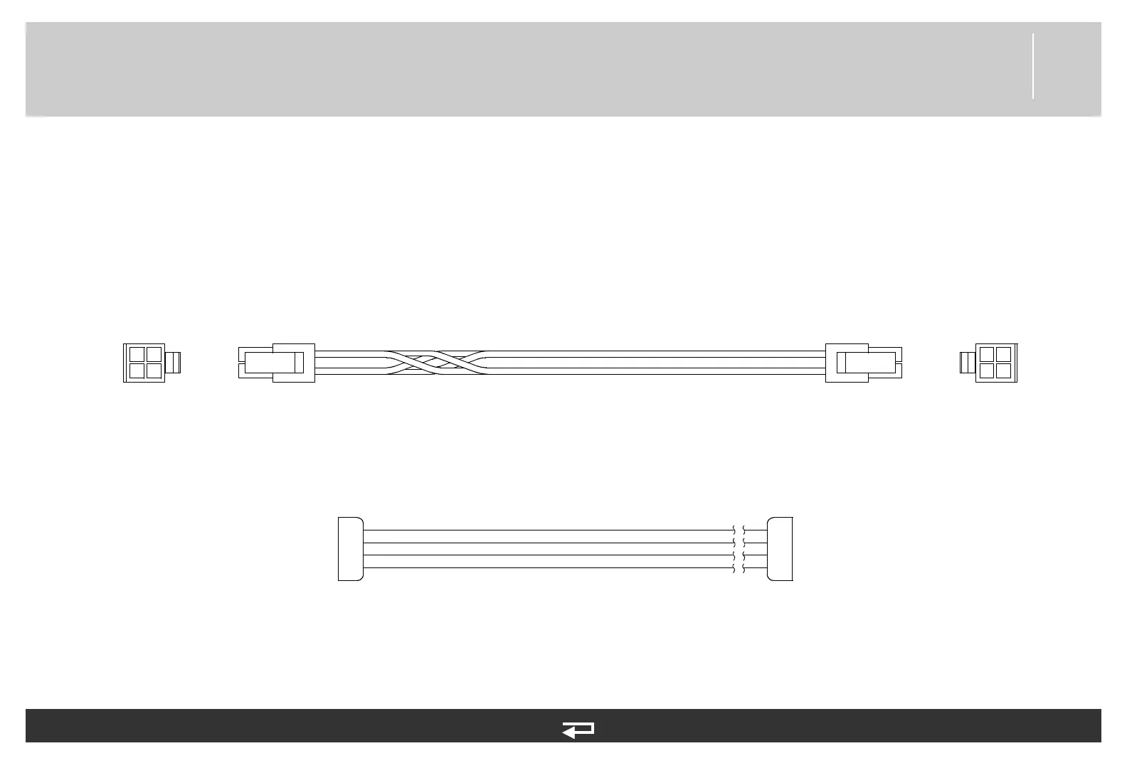
Power PCB/Therapy PCB Cable
Figure 9.42—Diagram for item W02
1
2
3
4
P08
1
2
3
4
P20
P08
1
2
3
4
P20
24
3
BLU
GRN
YEL
RED
1
GND
SW VB
GND
SW VB
Power PCB (p. 445)
Therapy PCB (p. 446)
Refer to Figure 9.17: Rear Case view 4 of 7, p. 403.
See MIN 3207692-000 in table for part information.