LIFEPAK 15 Monitor/Defibrillator
Service Manual
Assembly Diagrams and Parts Lists
Connection Diagrams for Assemblies, Control Boards, Cables, and
Connectors
Section Menu Section Contents
Back
Index
444
9
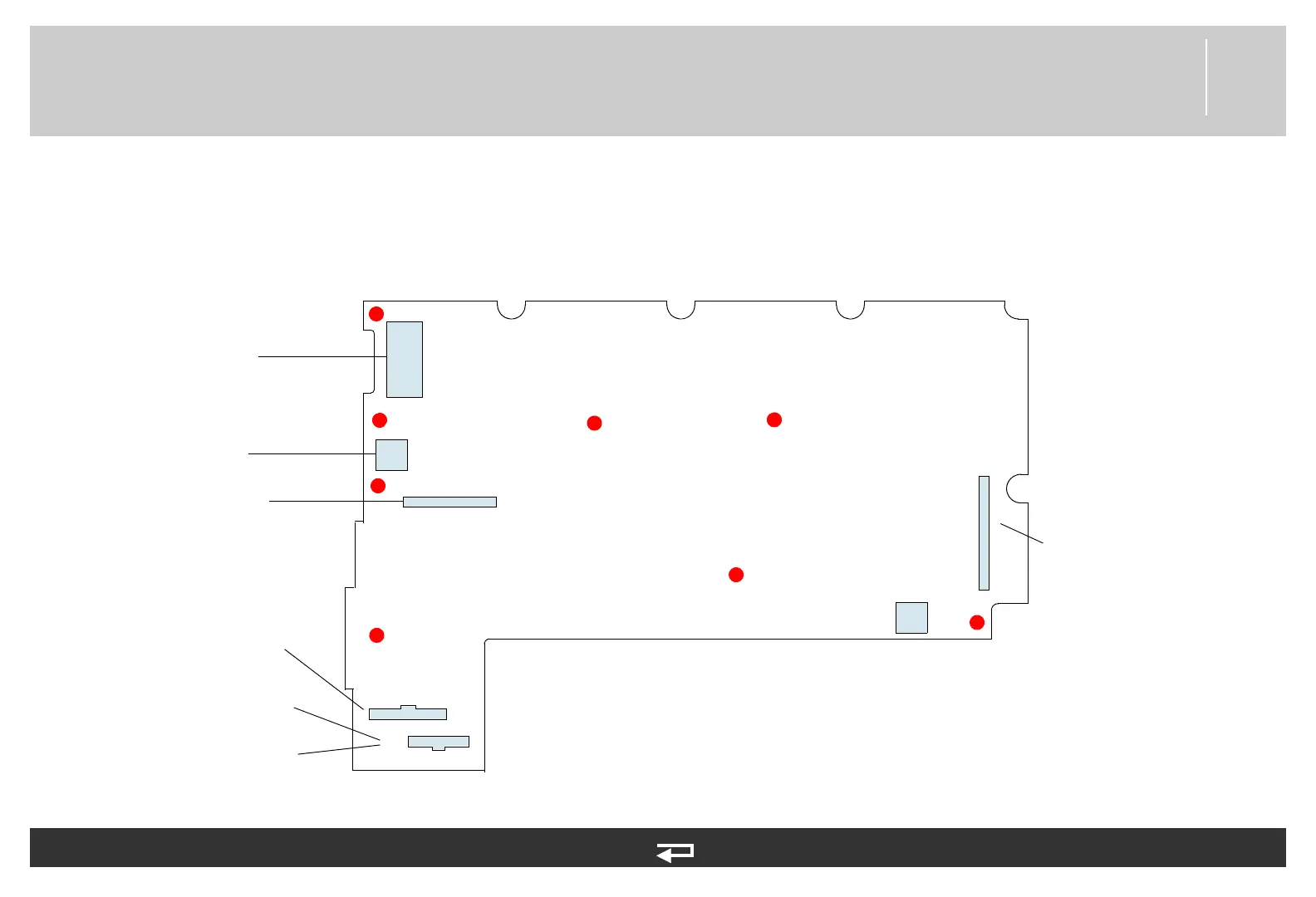
System PCB
Figure 9.22—Diagram for item A01
J2
J4
J5
J1
Power PCB/
Contact PCB
Cable (p. 467)
USB Flex
Assembly
(p. 476)
ECG Connector
Cable (p. 469)
System PCB/Interface
PCB Cable (p. 466)
System PCB/
Therapy PCB
Connector (p. 465)
Invasive Pressure
Assembly (p. 489)
J6
J7
J10
Refer to System/Therapy PCB Assembly Diagrams and Parts List (p. 387) and Figure 9.9: System/Therapy
PCB assembly view 2 of 2, p. 388
See also MIN 3206834 in table for parts information.
Temperature
Connector Cable