LIFEPAK 15 Monitor/Defibrillator
Service Manual
Assembly Diagrams and Parts Lists
Connection Diagrams for Assemblies, Control Boards, Cables, and
Connectors
Section Menu Section Contents
Back
Index
469
9
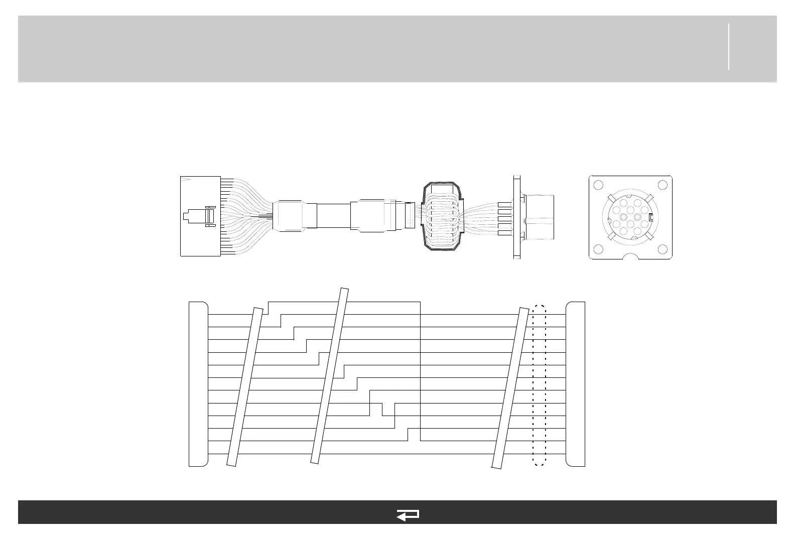
ECG Connector Cable
Figure 9.47—Diagram for item W07
E2
DRAIN
BROWN
BLACK
RED
YELLOW
BLUE
GRAY
DRAIN
ORANGE
GREEN
VIOLET
WHITE
1
2
3
4
5
6
7
8
9
10
11
12
RL
RA
LA
LL
V1
V2
V3
V4
V5
V6
12
P6
11
10
9
8
7
6
5
4
3
2
1
E1
P6
BLACK/RED
CBL
E3
ECG
connector
System PCB (p. 444)
Refer to Parameter Bezel Diagrams and Parts List (p. 392).
See MIN 3007991-007 in table for parts information.