LIFEPAK 15 Monitor/Defibrillator
Service Manual
Assembly Diagrams and Parts Lists
Connection Diagrams for Assemblies, Control Boards, Cables, and
Connectors
Section Menu Section Contents
Back
Index
470
9
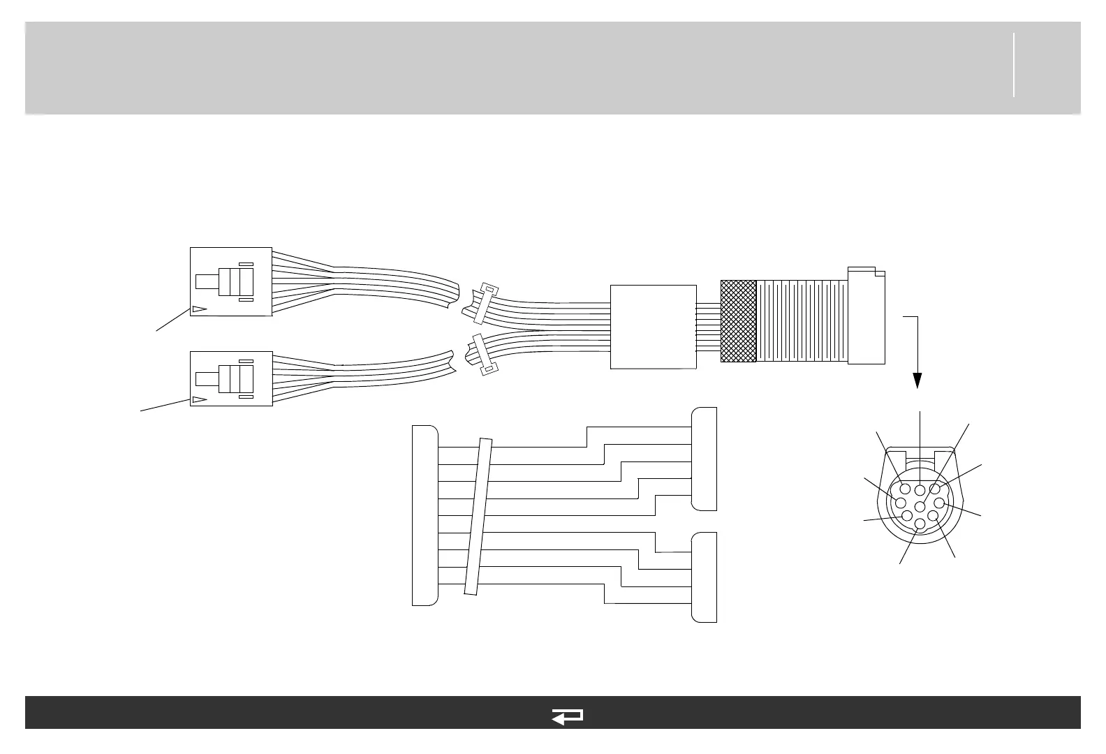
System Connector Cable
Figure 9.48—Diagram for item W08
2
1
3
4
5
6
7
8
9
1
2
3
4
5
1
2
3
4
P10
P9
P10
P09
BLU
GRN
YEL
BRN
ORN
GRN/WHT
YEL/GRN
WHT/BLK
E1
Pin 1
Pin 1
GND
SYS TX
SYS RX
SYS DTA
SYS CTS
SYS RTS
GND
ANALOG ECG
SW VB
system
PIN 1
PIN 2
PIN 3
PIN 4
PIN 5
PIN 6
PIN 7
PIN 8
PIN 9
front view
system
connector
Power PCB (p. 445)
Power PCB (p. 445)
connector
BLU/WHT
Refer to Figure 9.17: Rear Case view 4 of 7, p. 403.
See MIN 3009652-01 in table for part information.