LIFEPAK 15 Monitor/Defibrillator
Service Manual
Assembly Diagrams and Parts Lists
Connection Diagrams for Assemblies, Control Boards, Cables, and
Connectors
Section Menu Section Contents
Back
Index
467
9
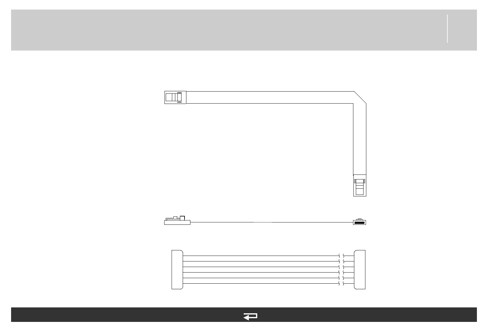
Power PCB/Contact PCB Cable
Figure 9.45—Diagram for item W05
1
2
3
4
5
6
1
2
3
4
5
6
ROW 0
COL 0
COL 1
COL 2
COL 3
GND
P42
P12
Power PCB (p. 445)
Contact PCB Module
Refer to Figure 9.17: Rear
Case view 4 of 7, p. 403.
See MIN 3207261-001 in
table for parts information.