LIFEPAK 15 Monitor/Defibrillator
Service Manual
Assembly Diagrams and Parts Lists
Connection Diagrams for Assemblies, Control Boards, Cables, and
Connectors
Section Menu Section Contents
Back
Index
462
9
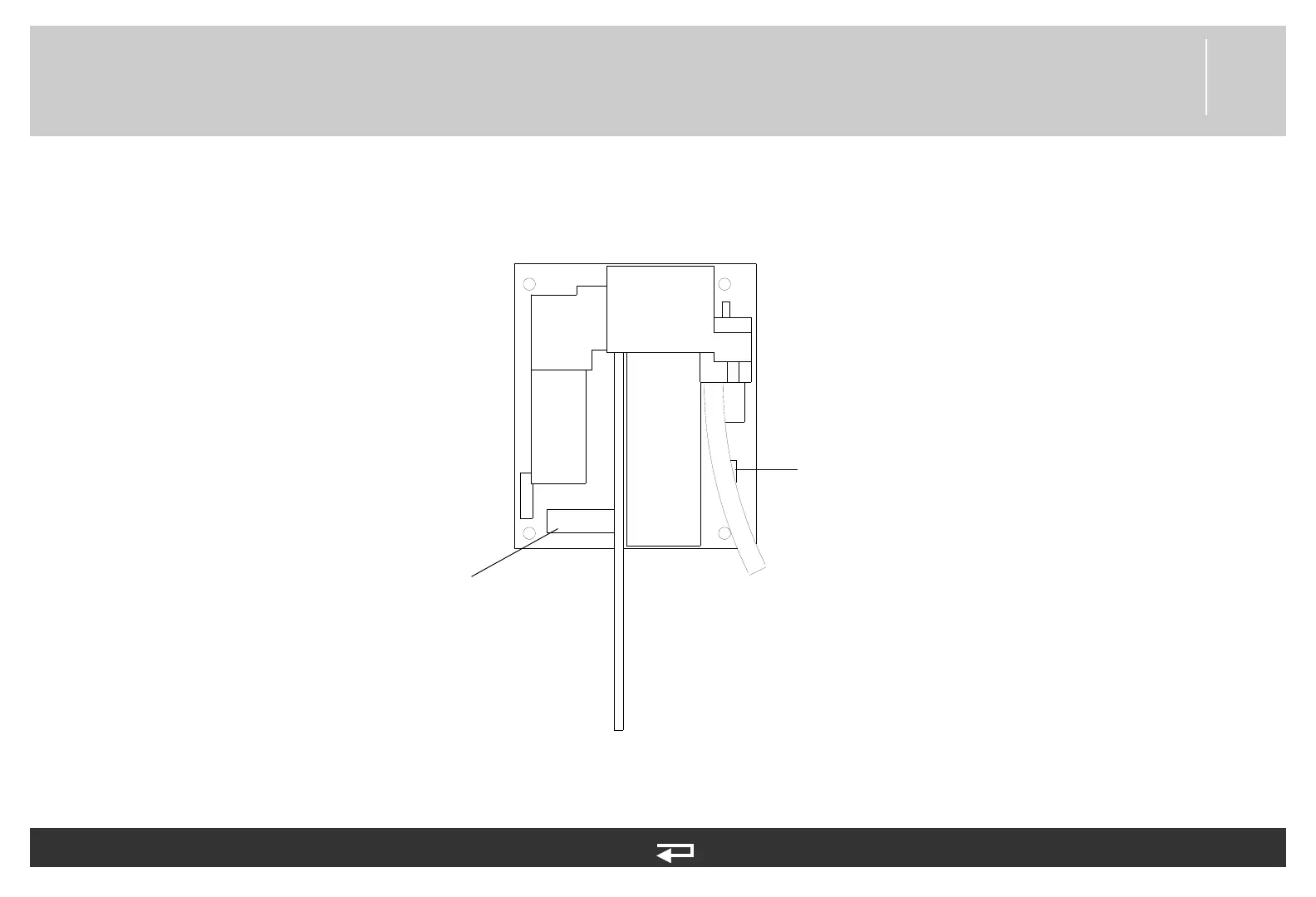
CO2 Module
Figure 9.40—Diagram for item A23
J1
J4
OEM PCB/SpO2 Module
Cable (p. 483)
CO2 Inlet Connector
Cable tubing
CO2 Inlet Connector
Cable (p. 487)
exhaust tubing
Refer to Figure 9.21: NIPB, CO2, and Sp02 view 1 of 1, p. 413.
See MIN 3012140-006 in table for parts information.