LIFEPAK 15 Monitor/Defibrillator
Service Manual
Assembly Diagrams and Parts Lists
Connection Diagrams for Assemblies, Control Boards, Cables, and
Connectors
Section Menu Section Contents
Back
Index
448
9
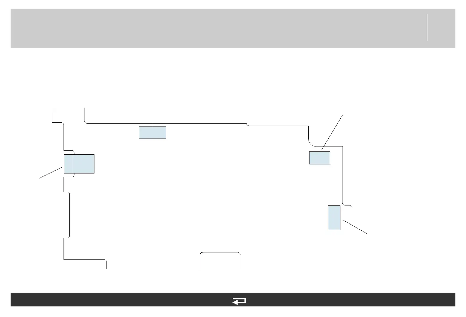
OEM PCB Module
Figure 9.26—Diagram for item A06
J25
Power PCB
(p. 445)
OEM PCB/SpO2 Module
Cable (p. 483)
J26
J27
J28
OEM PCB/CO2 Module
Cable (p. 485)
OEM PCB/NIBP
Module Cable
(p. 486)
Refer to Figure 9.18: Rear Case view 5 of 7, p. 404.
See MIN 3206813-003 in table for parts information.