LIFEPAK 15 Monitor/Defibrillator
Service Manual
Assembly Diagrams and Parts Lists
Connection Diagrams for Assemblies, Control Boards, Cables, and
Connectors
Section Menu Section Contents
Back
Index
486
9
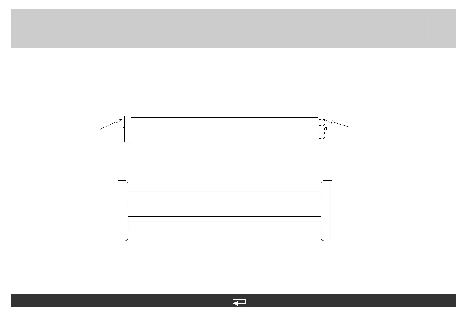
OEM PCB/NIBP Module Cable
Figure 9.64—Diagram for item W27
1
2
3
4
5
6
7
8
9
10
P28 P2
6V+
6V+
TX
KEY
GND
GND
6V+
GND
RX
NIBP_RES (Ext Reset)
6V+
6V+
TX
KEY
GND
GND
6V+
GND
RX
NIBP RES
1
2
3
4
5
6
7
8
9
10
NIBP Module (p. 460)
OEM PCB Module (p. 448)
P2
P28
Pin 1
Pin 1
Refer to NIPB, CO2, and Sp02 (p. 413).
See MIN 3012181-00 in table for part information.