LIFEPAK 15 Monitor/Defibrillator
Service Manual
Assembly Diagrams and Parts Lists
Connection Diagrams for Assemblies, Control Boards, Cables, and
Connectors
Section Menu Section Contents
Back
Index
472
9
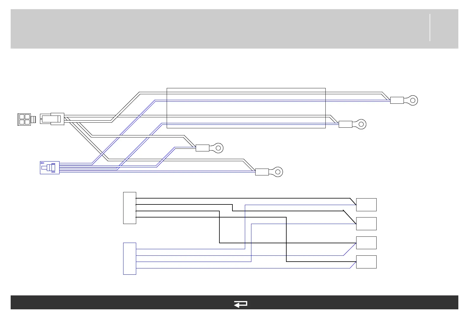
Battery Pins/Power PCB Cable
Figure 9.50—Diagram for item W10
4
3
2
1
1
2
3
4
P46
P45
P44
P43
Battery Well 2 +
Battery Well 2 -
Battery Well 1+
Battery Well 1-
RED
GREEN
BLUE
YELLOW
RED/WHT
BLUE/WHT
GREEN/WHT
YELLOW/WHT
P11
P13
2
1
3
4
P11
P13
P46
P45
P44
P43
Battery
Well 1+
Battery
Well 1-
Battery
Well 2-
Battery
Well 2+
Power PCB (p. 445)
Power PCB (p. 445)
Refer to Figure 9.17: Rear Case view 4 of 7, p. 403.
See MIN 3009726-08 or 3303863-000 in table for part information.
P13 connector is on the
3009726 cable assembly only.
The 3303863 cable assembly
is installed only in LIFEPAK 15
V2 with Aux. Power connector.