LIFEPAK 15 Monitor/Defibrillator
Service Manual
Assembly Diagrams and Parts Lists
Connection Diagrams for Assemblies, Control Boards, Cables, and
Connectors
Section Menu Section Contents
Back
Index
455
9
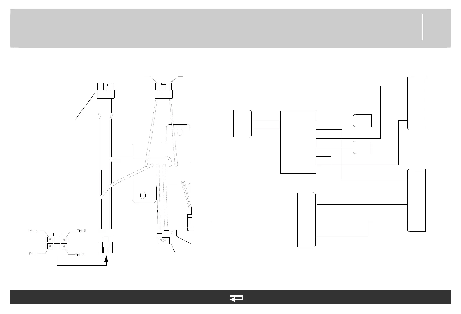
Transfer Relay Assembly
Figure 9.33—Diagram for item A13
1
P22
2
red
black
X1
X2
A13
A1
A2
A3
B1
B2
B3
7
104
P21
5
4
3
2
1
1
2
3
4
5
P24
6
5
4
3
2
1
wiring diagram
P18
Therapy PCB
(p. 446)
Therapy PCB
(p. 446)
Therapy
Connector
Cable (p.
473)
Interconnect
Bracket (p. 459)
Biphasic Module
(p. 461)
P21
P18
P22
P24
pin 5
pin 1
red
red
red
red
red
red
red
white
A3
B3
B2
B1
A2
A1
x2
x1
pin 1
Refer to Figure 9.18: Rear
Case view 5 of 7, p. 404.
See MIN 3201583-001 in
table for parts information.
Therapy PCB
(p. 446)