LIFEPAK 15 Monitor/Defibrillator
Service Manual
Assembly Diagrams and Parts Lists
Connection Diagrams for Assemblies, Control Boards, Cables, and
Connectors
Section Menu Section Contents
Back
Index
475
9
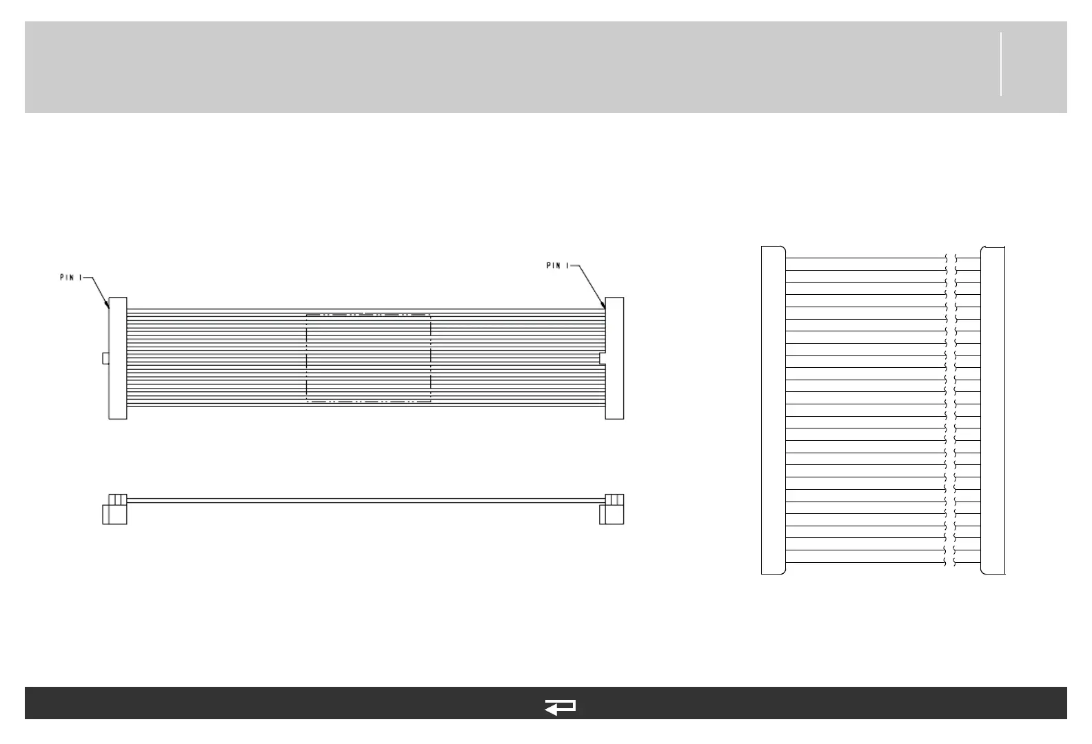
Main Keypad/Interface PCB Cable
Figure 9.53—Diagram for item W13
Interface PCB (p. 447)
Main Keypad (p. 452)
Refer to Figure 9.6: Front Case parts view 2 of 3, p. 379.
See MIN 3207388-001 in table for parts information.
P31
P39
1
2
3
4
5
6
7
8
9
10
11
12
13
14
15
16
17
18
19
20
21
22
23
24
25
26
26
25
24
23
22
21
20
19
18
17
16
15
14
13
12
11
10
9
8
7
6
5
4
3
2
1
P39P31
GND
PWR SW*
PWR LED
CHG LED
XREQ2
VCC
COL 4
COL 3
COL 2
SERVICE LED
COL 1
SHOCK LED
GND
SYNC LED
PACING LED
ALARMS LED
NIBP LED
ROW 2
ROW 3
ROW 4
ROW 5
COL 0
TRIM LED
ANALYZE LED
ADVISORY LED
ROW 1