LIFEPAK 15 Monitor/Defibrillator
Service Manual
Assembly Diagrams and Parts Lists
Connection Diagrams for Assemblies, Control Boards, Cables, and
Connectors
Section Menu Section Contents
Back
Index
477
9
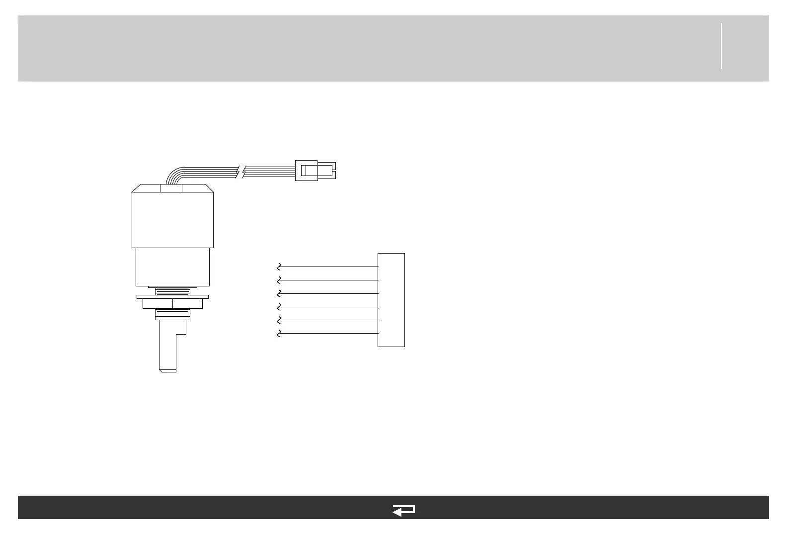
Speed Dial Assembly
Figure 9.55—Diagram for item W15
Interface PCB (p. 447)
Refer to Figure 9.6: Front Case parts view 2 of 3, p. 379.
See MIN 3011128-002 in table for parts information.
P33
6
5
4
3
2
1
P33
ENC ON
ENC0 IN
ENC1 IN
ENC SW1
ENC SW2
GND
selector