LIFEPAK 15 Monitor/Defibrillator
Service Manual
Replacement Procedures
Transfer Relay Assembly (A13) Replacement
Section Menu Section Contents Procedures Back Index
269
8
Removing the Transfer Relay Assembly (A13)
To remove the Transfer Relay Assembly from the rear case:
1. Disassemble the case as described in Disassembling the Case (p. 181).
2. Remove the system/therapy PCB assembly as described in System
(A01)/Therapy (A04) PCB Assembly Replacement (p. 232).
3. Remove the screw (202253-761) securing the clear, plastic, high-
voltage shield (3010593-00) from the interconnect bracket (A17).
Discard the screw.
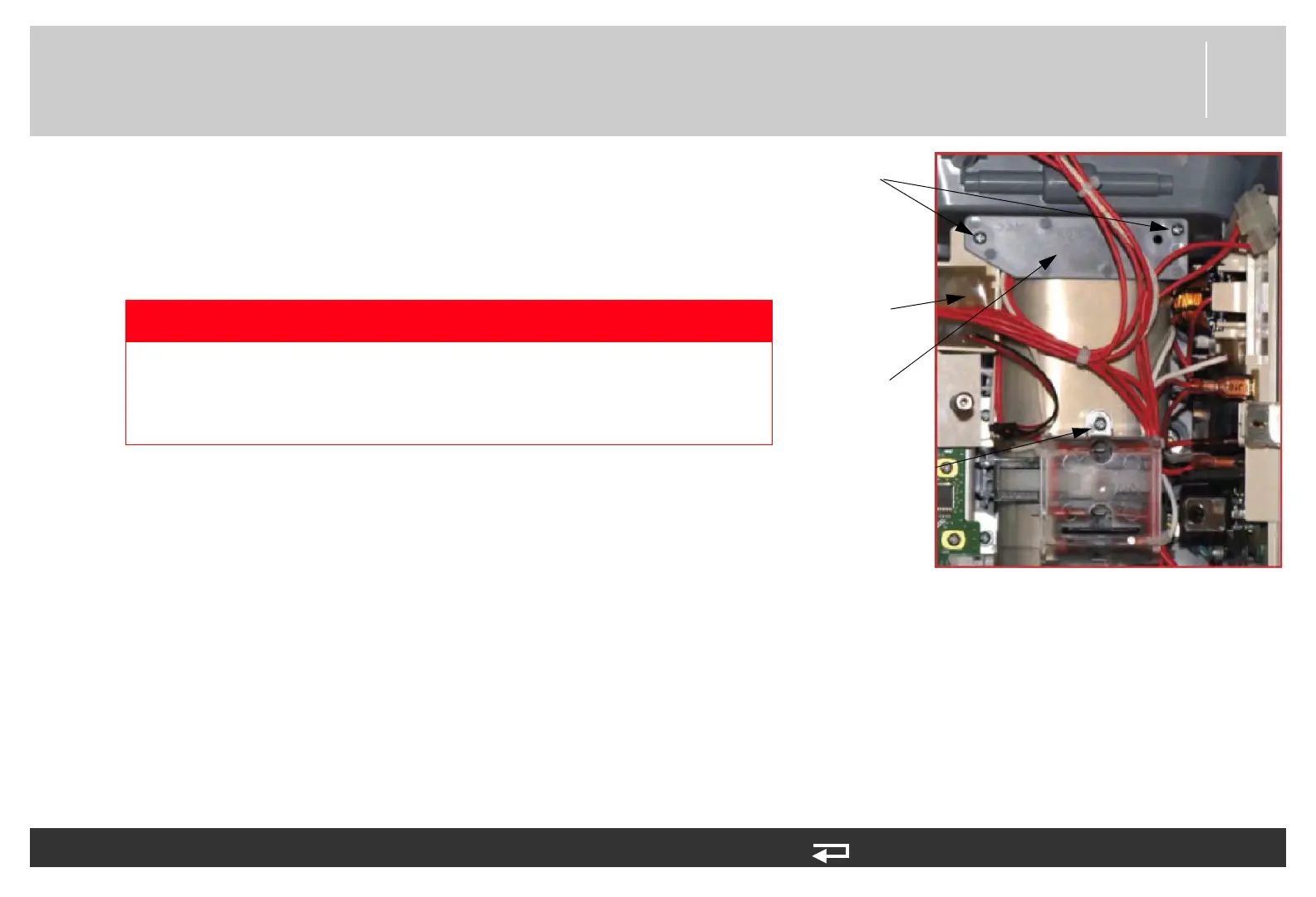
4. Remove the two mounting screws (202253-761) from the capacitor
bracket and remove the bracket (3207031-001). Discard the screws.
5. Carefully cut six small cable ties to free the high voltage relay wires
from the rear case.
6. Disconnect the white transfer relay lead from the interconnect bracket at pin 7. Needle nose pliers may be used to assist in
disconnection.
7. Remove the two biphasic module mounting screws (3207337-312). Discard the screws.
8. Lift the biphasic bracket up slightly to gain access to connector. Disconnect the red transfer relay lead spade connector from the
biphasic modular assembly at J104. Needle nose pliers may be used to assist in disconnection.
9. Lift the high voltage relay out of the rear case.
DANGER
SHOCK HAZARD Lethal voltages may be present even without
operator action. Always discharge the energy storage capacitor
prior to servicing. See the service manual “Capacitor Discharging
Procedure (p. 178)” for detailed instructions.
capacitor
bracket
two screws
high voltage
relay
cover screw
Figure 8.65—Transfer relay parts and screw locations