LIFEPAK 15 Monitor/Defibrillator
Service Manual
Replacement Procedures
NIBP (A21)/CO2 (A23) Module Replacement
Section Menu Section Contents Procedures Back Index
297
8
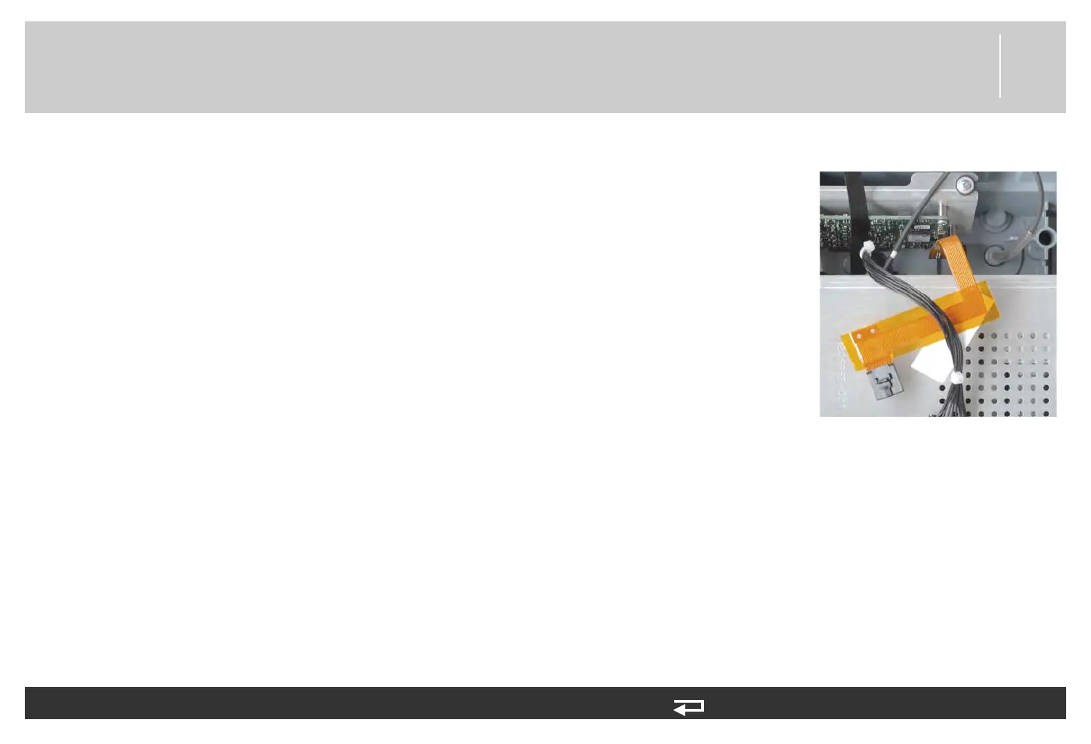
8. If present, connect the exhaust tube to the rear case outlet connector.
9. Install the OEM PCB as described in Installing the OEM PCB (A06) (p.
265).
10. Install the transfer relay assembly as described in Installing the Transfer
Relay Assembly (A13) (p. 270).
11. Install the system/therapy PCB assembly as described in System (A01)/
Therapy (A04) PCB Assembly Replacement (p. 232).
12. Reassemble the case as described in Reassembling the Case (p. 184).
To install the A21 NIBP, A23 CO2, and SpO2 PCBs: (Continued) 12 steps, (Page 6 of 6)
Figure 8.93—CO2 exhaust tube connection