LIFEPAK 15 Monitor/Defibrillator
Service Manual
Replacement Procedures
OEM PCB (A06) Replacement
Section Menu Section Contents Procedures Back Index
265
8
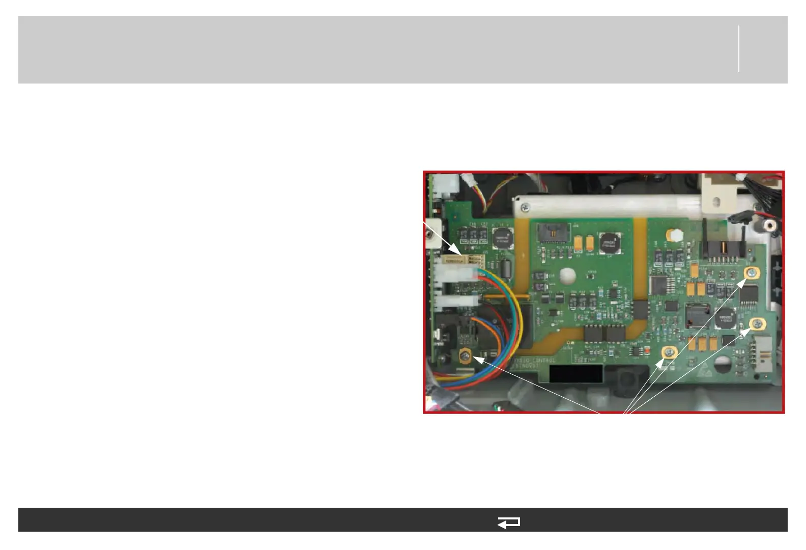
Installing the OEM PCB (A06)
Refer to Inside Rear Case Diagrams (p. 228).
To install the OEM PCB (A06) into the rear case: 12 steps, (Page 1 of 3)
NOTE: When installing a new OEM PCB, use
either the OEM PCBA Repair Kit, V1
(MIN 3305431-004) (p. 498) or OEM
PCBA Repair Kit, V2 (MIN 3305431-
028) (p. 516).
1. Lift the tab at the upper left corner of the
OEM PCB over the ground clip on the power
bracket, and then press down on the tab
while sliding the OEM PCB to the left to
engage the direct connection (J25) to the
A03 power PCB at J16.
2. Ensure that the ground tab of the OEM PCB
is above the power PCB bracket. Ensure the
OEM PCB sits flat on the OEM bracket and
presses straight into the power PCB.
3. Install four new screws (202253-761);
torque to 6.8 in-lb.
J25 connector
mounting screws
(4 places)
Figure 8.62—OEM PCB screw locations