Chapter H - FOOT CONTROL
Planmeca Compact i H-13
ADJUSTMENTS
Technical Manual
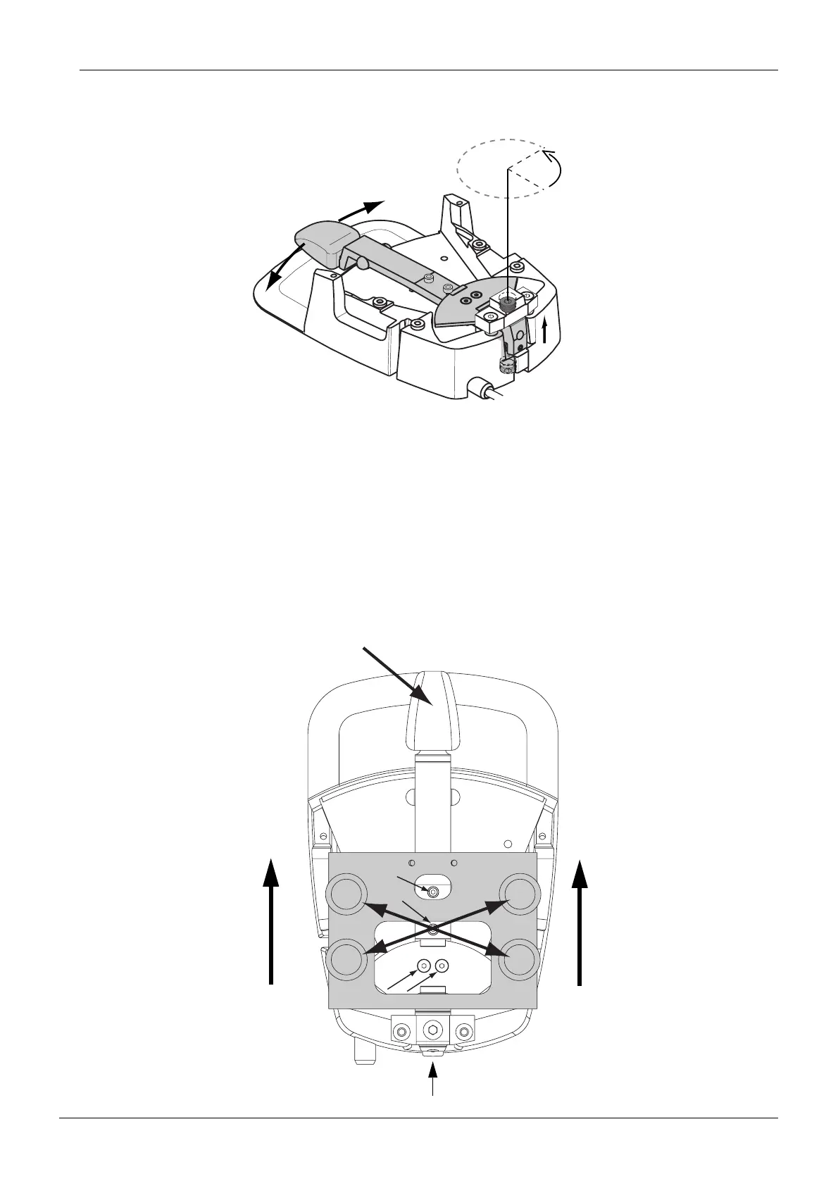
f) Then loosen the upper adjustment screw approx. 1/4 turn so that the foot control pedal can
move freely.
g) Push the foot control pedal downwards and lock it to this position as follows. Tighten the
angle adjusting screw located on the back of the pedal arm first completely and then loosen
the screw 1/4 turn (see figure on page H-14).
h) Check that the screws of the sector plate and pedal centering plate are loose.
i) Place the foot control calibration tool over the foot control so that the attachment screws go
into the Foot control PCB attachment holes. Remove the play of the calibration tool
attachment by pushing the calibration tool towards the pedal end as shown on the figure
below. Make sure that the calibration tool is not tilted.
j) Tighten the attachment screws gradually as follows. First tighten the screws number one and
two slightly and then screws three and four, and then again screws one and two etc. until the
screws are completely tightened.
k) Release the pedal from the lower position by loosening the angle adjusting screw.
Fcntrl5.eps
1/4 round
approx. 1/4 turn
1
3
4
2
Fcntrl6.eps
Push the pedal downwards and tighten the
angle adjusting screw.
Remove the play.