Polycom RealPresence Collaboration Server (RMX)1500/2000/4000 Deployment Guide for Maximum Security Environments
1-30 Polycom, Inc.
2 Click the Next button.
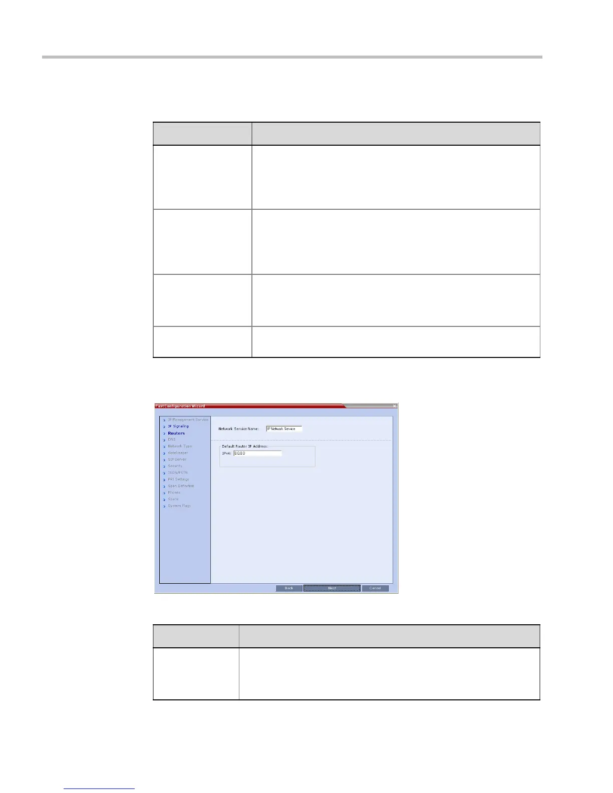
3 Enter the required Routers information in the dialog box.
Table 1-4 Signaling Network Service – IP Signaling
Field Description
Network Service
Name
The name Default IP Service is assigned to the Signaling Network
Service by the Fast Configuration Wizard. This name can be
changed.
Note: This field is displayed in all IP Signaling dialog boxes and can
contain character sets that use Unicode encoding.
Signaling Host IP
Address
Enter the address to be used by IP endpoints when dialing into the
MCU.
Dial out calls from the RMX are initiated from this address.
This address is used to register the RMX with a Gatekeeper or a SIP
Proxy server.
Media Card 1-4
IP Addresses
Enter the IP address(es) of the media card (s) (MPM+/MPMx 1 and
MPM+/MPMx 2-4 (if installed)) as provided by the network
administrator. Endpoints connect to conferences and transmit call
media (video, voice and content) via these addresses.
Subnet Mask Enter the subnet mask of the MCU.
Default value: 255.255.255.0.
Table 1-5 Signaling Network Service – Routers
Field Description
Default Router
IP Address
Enter the IP address of the default router. The default router is used
whenever the defined static routers are not able to route packets to their
destination. The default router is also used when host access is
restricted to one default router.