28
7. For RFID models only: Turn the media damper guide locking knob counterclockwise just enough
to slide the media width guide, and no more.
8. For RFID models only: Position the media width guide lightly against the outside edge of the
installed media and tighten the locking knob by turning it clockwise.
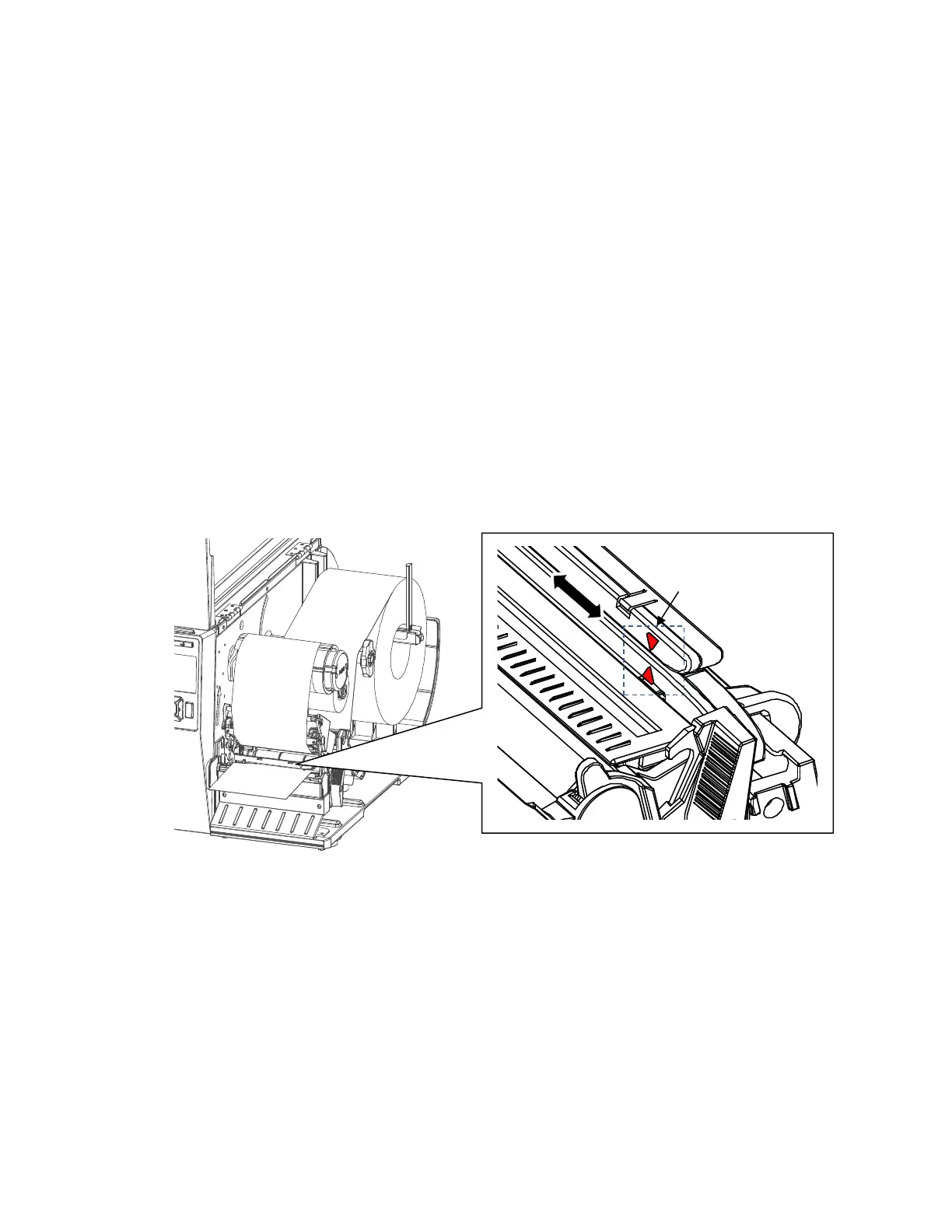
9. Slide the media sensor assembly so that the media sensor(s) are placed in the path of the desired
label length indicators (liner gaps, notches, holes or black marks) on the media. The next page
shows the position of media sensor assemblies. The sensor location is indicated by a triangle
mark ▽ on the sensor housing. Notice that the 4” model has one sensor assembly that detects
gaps, notches, holes and black marks while the 6” model has two separate assemblies, an inboard
assembly for detecting only gaps, notches or holes and an outboard for detecting only black
marks.
NOTE: Your printer is equipped with media sensors that detect the top-of-form position on media with
label length indicators (gaps, notches, holes, or black marks). These sensors also detect when
a Paper Out condition exists. For more details and settings, please see “Positioning the Media
Sensors” section on page 35.
For 4” width model