Drawings
124 Rev. B4 Feb 2015 CS210
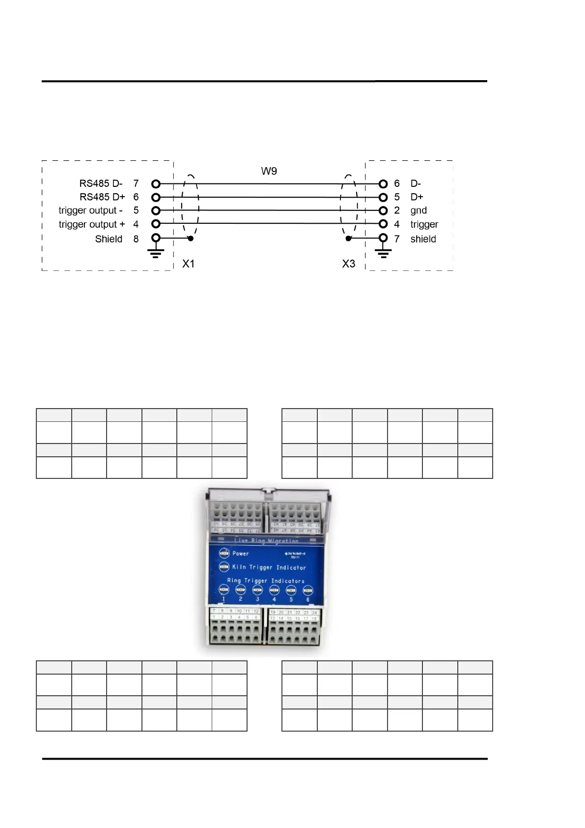
13.8.2 Terminal Wiring W9
Figure 116: Wiring of W9 between LRM Remote Control Box and System Connection Box
13.8.3 Internal Wiring for the Position Indicators 4, 5, 6
The internal wiring for the position indicators 4, 5, 6 does not come as factory default. If you want to
run your system with these additional position indicators then you have to realize the internal wiring
by your own. The complete wiring for the LRM Remote Control Box is given below.
Trigger
out
out
out
out
Scanner
out
out
out
out