Installation
CS210 Rev. B4 Feb 2015 23
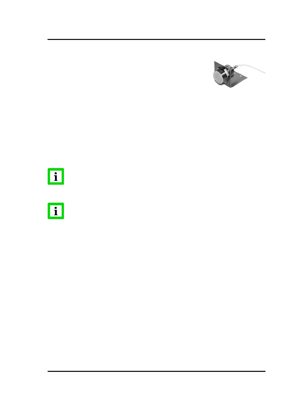
5.4 Position Indicator
The position indicator is a temperature resistant inductive proximity
switch used to synchronize the scanning system with the kiln rotation.
The position indicator consists of two parts, a high temperature sensor
head, and a junction box. Since the maximum ambient temperature
allowed is 230°C (446°F), the sensor may be mounted near the kiln’s
surface. For the junction box a maximum ambient temperature of 70°C (158°F) is allowed. For further
technical details see appendix 14.5 Position Indicator, page 131.
Both components, sensor and junction box, are connected via a high temperature cable (length: 5 m /
15 ft). Protecting the cable against mechanical stress is recommended. Since the position indicator is
necessary to generate a trigger pulse for the CS210 system, a trigger bar must be welded onto the
“colder“ end of the kiln and if possible close to the drive ring (see Figure 9).
The distance between the trigger bar and the position indicator is a very important parameter for
correct operation. If the distance is too small, the trigger bar can destroy the sensor head. On the other
hand, if the distance is too big, the position indicator will be unable to detect the trigger bar. Thus, it
will not be able to generate the trigger pulse for the system.
In the case of a non-existing trigger signal, the system switches to the non-synchronized
mode. In this mode, a yellow bar on the top area in the CS
continuously. Non-synchronized thermograms are not stored in the database!
In multi-scanner systems, the trigger signal may be associated with any scanner!