Accessories
90 Rev. B4 Feb 2015 CS210
10.6 Shadow Monitoring
The linescanners can be hindered from monitoring the complete kiln by physical obstructions and also
by shadows from the tires. With the Shadow Monitoring Package (XXXTCS200SM) up to 32 additional
pyrometers can be installed and configured to monitor these “shadowed” portions. The temperature
values from these pyrometers are integrated in the scanned data from the linescanners and the results
are displayed as one homogenous thermogram.
For an overview of a system configured with Shadow Monitoring, see section 13.2 CS212 Installation
with Accessories, page 115.
Delivery:
• MI310LTH sensor and MI3 Communication Box (metal) with RS485 communications
• Air purge jacket, stainless steel
• Adjustable mounting bracket
• MI connection box
Mounting:
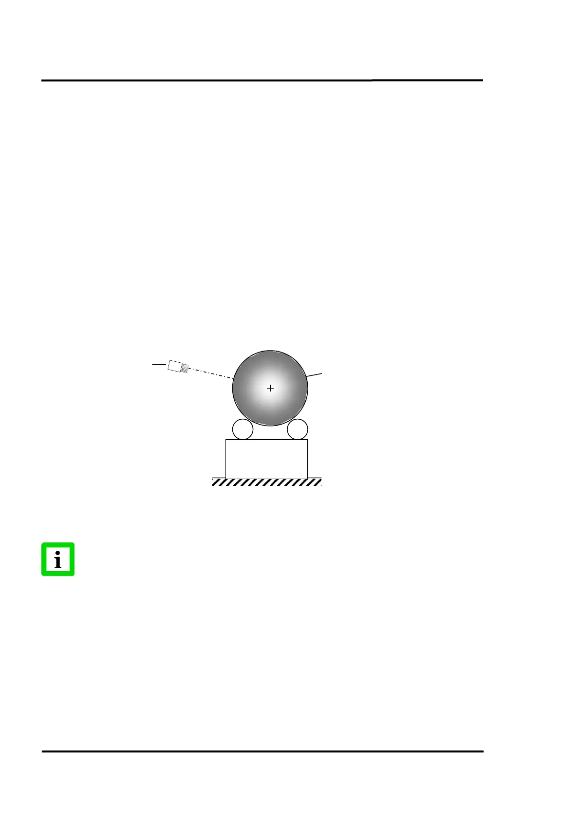
The recommended MI3 sensor mounting is shown in the figure below. The angular alignment of the
sensor head reduces the risk of possible contaminations on the optics.
Figure 88: Recommended Alignment of MI3 Sensor
Make sure that the resulting spot size for the MI3
sensor covers the size of the
shadowed area!
Example:
Optical resolution for the MI3 sensor: 10:1
Distance to the kiln 5000 mm (200 in.)
Resulting spot size: 500 mm (20 in.)
Wiring:
For an installation of two or more shadow sensors in a network, each MI3 communication box is
wired parallel to the others. You may connect up to 32 units. Make sure to deactivate the preset shunt
resistor for all units except for the last one in the chain. The switch for activating the shunt is found on