Installation
20 Rev. B4 Feb 2015 CS210
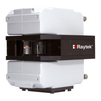
Figure 6: Cable installation
Using the 4 M5x25 screws, mount the grommet plate on the outside of the protective housing. Plug
the cable connectors into the linescanner. Connect the socket and the plug for earth ground.
If installing the CS210 system in a warm environment, water-
cooling may be necessary.
The tubes used for water may be run through the second grommet plate!
5.2 System Connection Box
The system connection box connects all device field cables with the customer supplied optical fibre
cable. The system connection box includes the Fibre Optic / RJ45 Ethernet Converter, the 24 VDC
power supply and the Serial/Ethernet converter for supporting the accessories (if used).
The box is supplied with quick installation line-up terminals. For more technical data, see section
14.2 Connection Box, page 128.
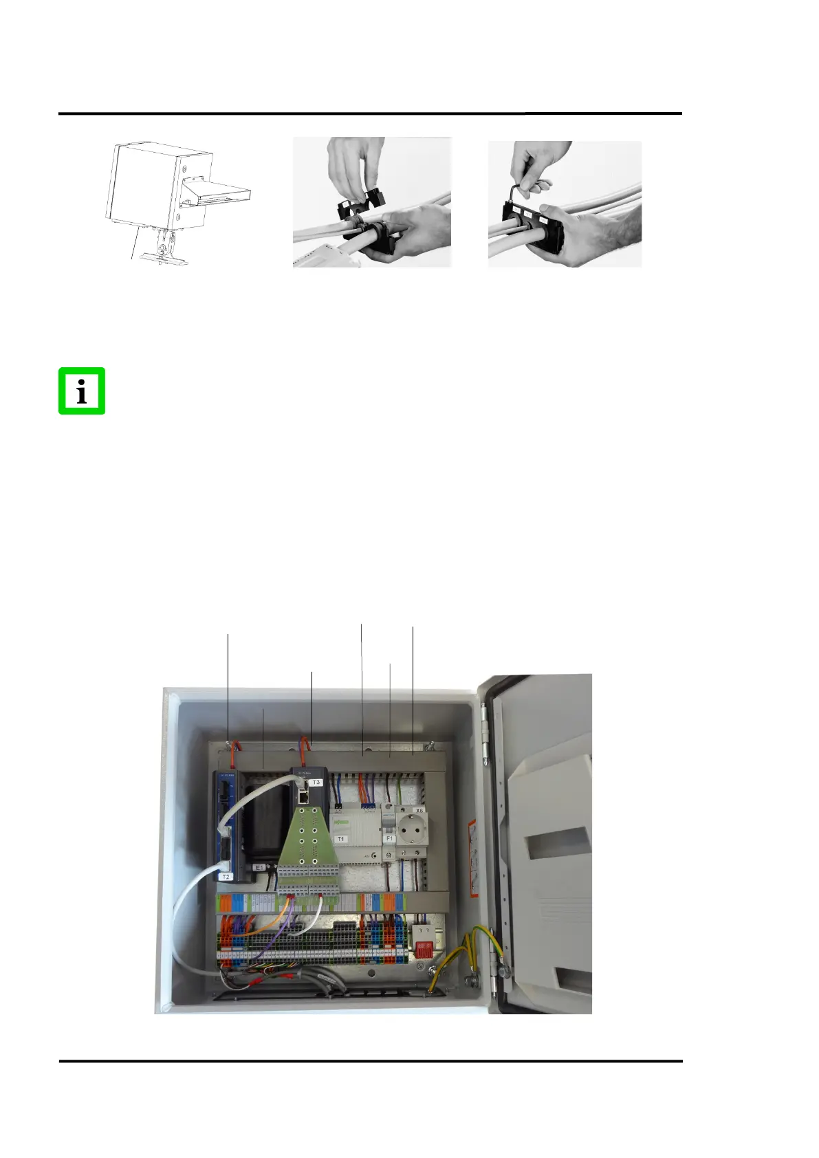
Figure 7: Opened System Connection Box
Converter
(Accessory)
RJ45 Ethernet
Converter
(Accessory)