Installation
CS210 Rev. B4 Feb 2015 21
Installation
The system connection box can be mounted up to 7 meters (23 ft) away from the scanner. However to
simplify aiming the scanner at the kiln it is the best that the connection box is mounted as close to the
scanner as possible. The cables between the linescanner and the connection box needs to be protected
from mechanical damage.
Mount the connection box in a convenient location. The cables W1, W2, W3, and W18 are factory
preinstalled. Insert the cable W20 using the grommet plate taking care to select the correct grommet
size for the cable diameter.
Connect the cables for the accessories with the connectors of the line-up terminal as described in
section 13.4 System Connection Box Wiring, page 117.
After double-checking all connections, switch the power on. The 24V-LED indicates the ON/OFF
status (see terminal pin 8 in the system connection box). Check the trigger signal coming from the
position indicator (see terminal pin 40 in the system connection box).
Pins 17 and 18 of the terminal in the system connection box connect to the internal alarm relay of the
scanner. The contacts are potential free, the maximum load is 30 V / 1 A. To configure the alarm relay,
see section 6.2.4.1 <Settings> for Scanner or Pyrometer, page 36.
Figure 8: Connection to the internal Alarm Relay of the Scanner
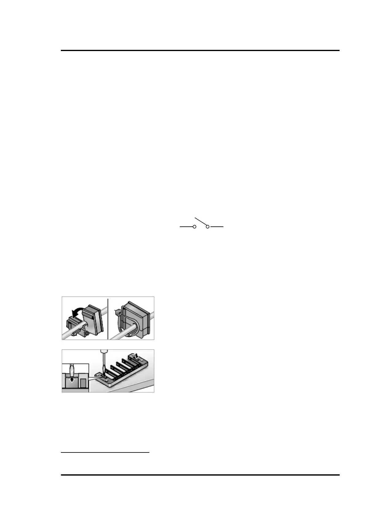
5.2.1 Cable Entry System
The cable entry system is a split system that allows pre-assembled cables to be routed into the system
connection box without disassembling the connectors.
Snap-on mounting
4
Lay cable into appropriate grommet and provide strain relief
where necessary using cable ties.
Use appropriate tool to punch through cover on base frame.
4
Illustrations: © Murrplastik