Pre-Installation
14 Rev. B4 Feb 2015 CS210
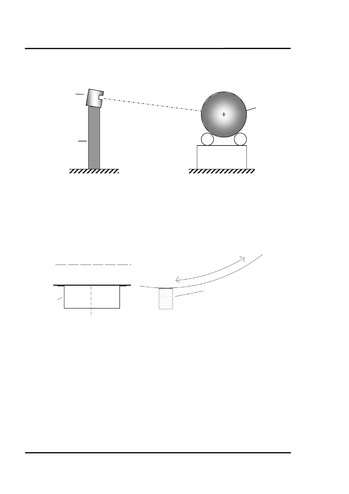
4.3 Scanner Alignment
The optimal scanner alignment is shown in the figure below.
Figure 2: Alignment of Scanner
4.4 Trigger Bar
A position indicator is mounted on the “colder” end of the kiln and generates a trigger pulse once per
revolution to supply the CS210 system with data on the rotational speed of the kiln. The installer must
mount a trigger bar onto the kiln shell as shown in the figure below.
The maximum ambient temperature for the position indicator is 230°C (446°F). For installing the
position indicator see section 5.4 Position Indicator, page 23.
Figure 3: Welding the Trigger Bar on the Kiln
4.5 Cable Requirements
The following cables are necessary for standard installations, see also system drawings given in
section 13.1 CS212 Installation without Accessories, page 114.
– W1 power supply cable for scanner (preinstalled with system connection box)
– W2 RS485 communication cable for scanner (preinstalled with system connection box)
– W3 trigger/alarm cable for linescanner (preinstalled with system connection box)
– W8 from the junction box of the position indicator to the system connection box (standard
installation) or to LRM remote control box (when used with accessory Live Ring Migration).
– W9 from the LRM remote control box to the system connection box. This six-wire-cable is used for
data communication, power supply, and trigger pulse.
Scanner stand
(dedicated tower or
roof of a building)