Configuration
46 Rev. B4 Feb 2015 CS210
after the first incident. If the next revolution also exceeds the limits, then an alarm will be generated
indicating that the system is outside control limits.
It is also possible to assign a digital alarm output for each ring. This one output will activate
immediately when an alarm is generated and will deactivate once the system returns to a level within
the user-defined tolerances and the alarm is cancelled.
6.2.10 <Digital Output Management>
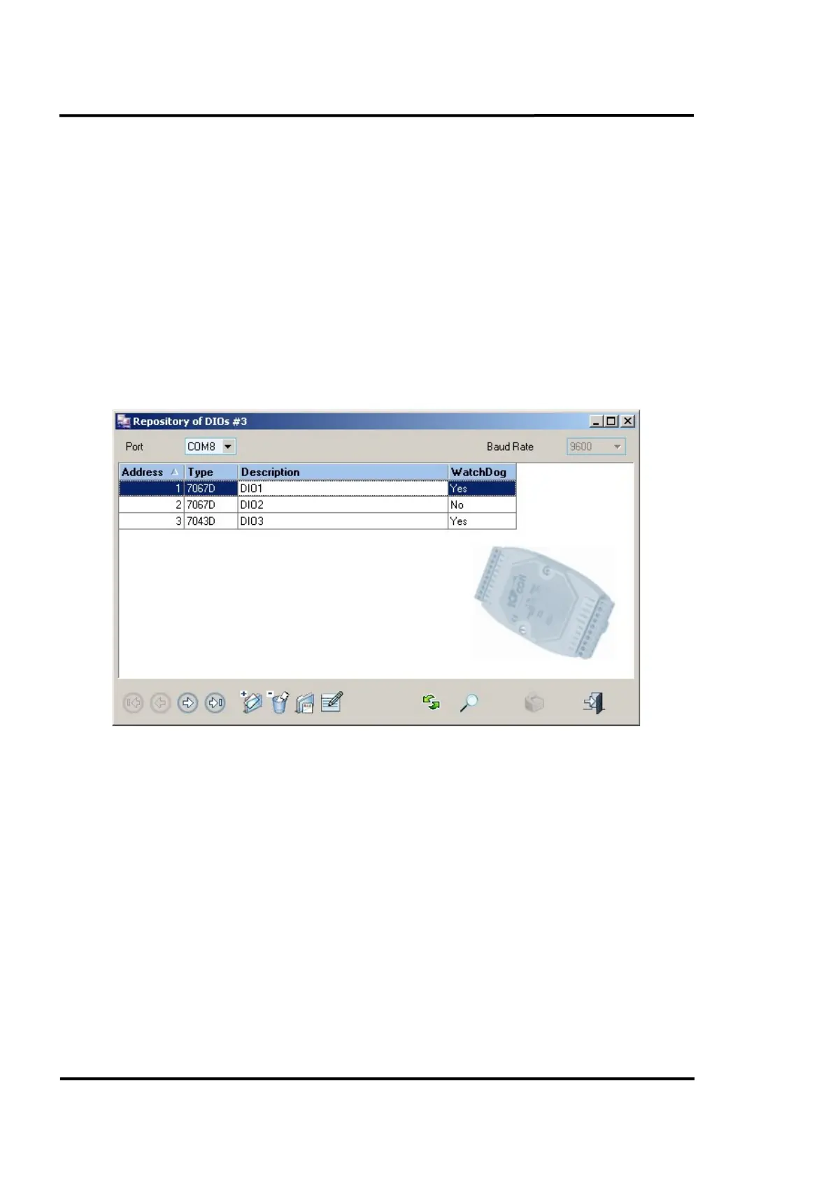
6.2.10.1 Repository of Digital Outputs
This repository shows all digital outputs in the system. The buttons along the lower toolbar let you
make new digital output entries, as well as deleting or editing existing entries by inputting the
appropriate details.
The same screen also lets you specify the port that the system must use in order to establish
communication with the digital output. The communication baud rate will always be 9600.
Figure 38: Repository of Digital Outputs
6.2.10.2 Digital Output Management detail
Clicking on any entry will open the detail dialogue box which shows all the possible features for each
single digital output: network address, description, type, WatchDog configuration and PowerOn
value.
By setting the WatchDog value, the user can define an output value that will be acquired by a digital
output when, for whatever reason, it loses contact with ReadScan for a period of time longer than the
<Watchdog timeout> which can also be defined by the user. In the given dialog box below, output
channel 3 switches from off to on after the <WatchDog timeout>.
The PowerOn value will be the output value that a digital output acquires when starting up.
More technical data for the available output modules are described in appendix see section
14.6 Output Modules, page 132.