Installation
24 Rev. B4 Feb 2015 CS210
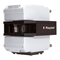
Figure 9: Mounting the Position Indicator
Adjustment of the position indicator:
1. Mount the trigger bar.
2. Mount the position indicator mounting plate .
3. Check the distance between position indicator and trigger bar.
4. Lock the position indicator in place and monitor its’ operation. With each revolution of the
kiln you should obtain a trigger pulse indicated by an LED in the junction box (field).
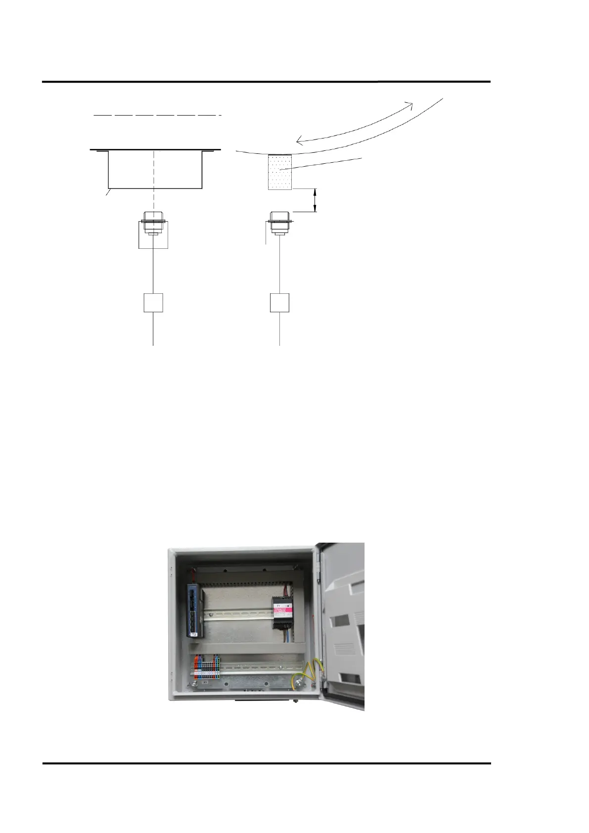
5.5 Fibre Optic Converter Box
The Fibre Optic Converter Box is located in the control room and connects the fibre optic cable from
the field to the Ethernet interface of the computer. For more technical data, see section 14.2 Connection
Box, page 128.
Figure 10: Fibre Optic Converter Box
, sized 50 mm in
in. in square)
Distance: max. 20 mm (0.79 in.)
Position indicator with
mounting pla
te
Cable W8 to system connection box