Accessories
CS210 Rev. B4 Feb 2015 89
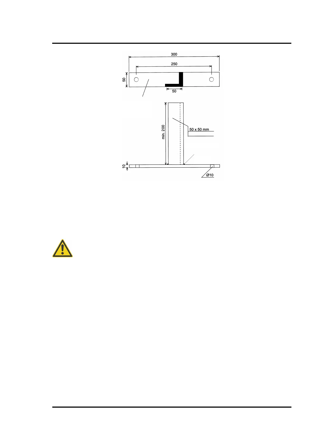
Figure 87: Trigger Bar – details –
10.5.4 Wiring
For the detailed wiring of the LRM see section 13.8 LRM Wiring, page 122.
For recommended cables see section 4.5 Cable Requirements, page 14.
The CS210 position indicator (master) must be wired to the <kiln trigger> labeled input
on the terminal line of the LRM remote control box
! All subsequent LRM position
indicators must be wired to the inputs <Ring 1>, <Ring 2> and so.
Flat Iron
(steel ST37)
Angle Iron