Installation
CS210 Rev. B4 Feb 2015 19
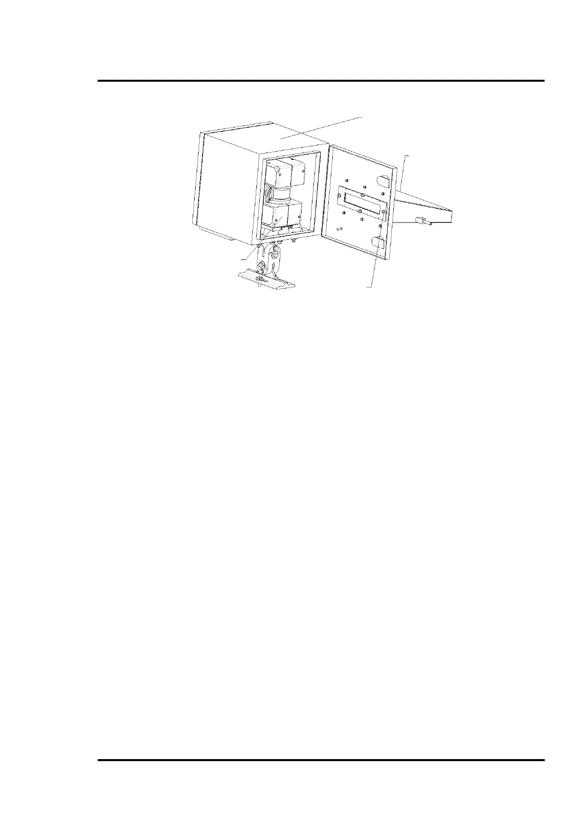
Figure 5: Protective housing with protective channel
Installing the linescanner
Open the back door. Insert the linescanner (with the mounted carrier) into the rail/carrier system. Lock
in the linescanner in place with the latches and screw.
Electrical Installation
For best performance, the electrical installation of the CS210 System should correspond to one of the
recommended installation configurations illustrated in section 13.1 CS212 Installation without
Accessories, page 114.
Connecting the cables
The cables W1, W2, W3, and W18 (located between the linescanner and the system connection box) are
factory preinstalled and supplied along with the system connection box.
For running the cables through the protective housing: open one grommet plate (on the bottom of the
protective housing) by loosening the three Allen-bolts. Use an appropriate grommet by considering
the different cable outer diameters:
• Cable W1 (power supply): Ø 5 mm (0.2 in)
• Cable W18 (Ethernet): Ø 6 mm (0.24 in)
• Cable W2 (RS485) and W3 (Alarm/Trigger): Ø 7 mm (0.28 in)
Feed the cable through the grommets so that grommet is approximately 400 mm (15.7 in) away from
the linescanner connectors (round plugs). Place the grommet plate over the grommets as shown in the
figure below. Be careful to have the cable identification plates pointed toward the system connection
box (longer end of the cables). Close unused holes with the blind grommets then close the grommet
plate.
Window holder
2 nuts – M6