Configuration
CS210 Rev. B4 Feb 2015 37
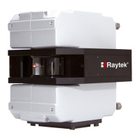
Figure 25: Definition of the Scanner device
On scanners only, you can define these additional parameters:
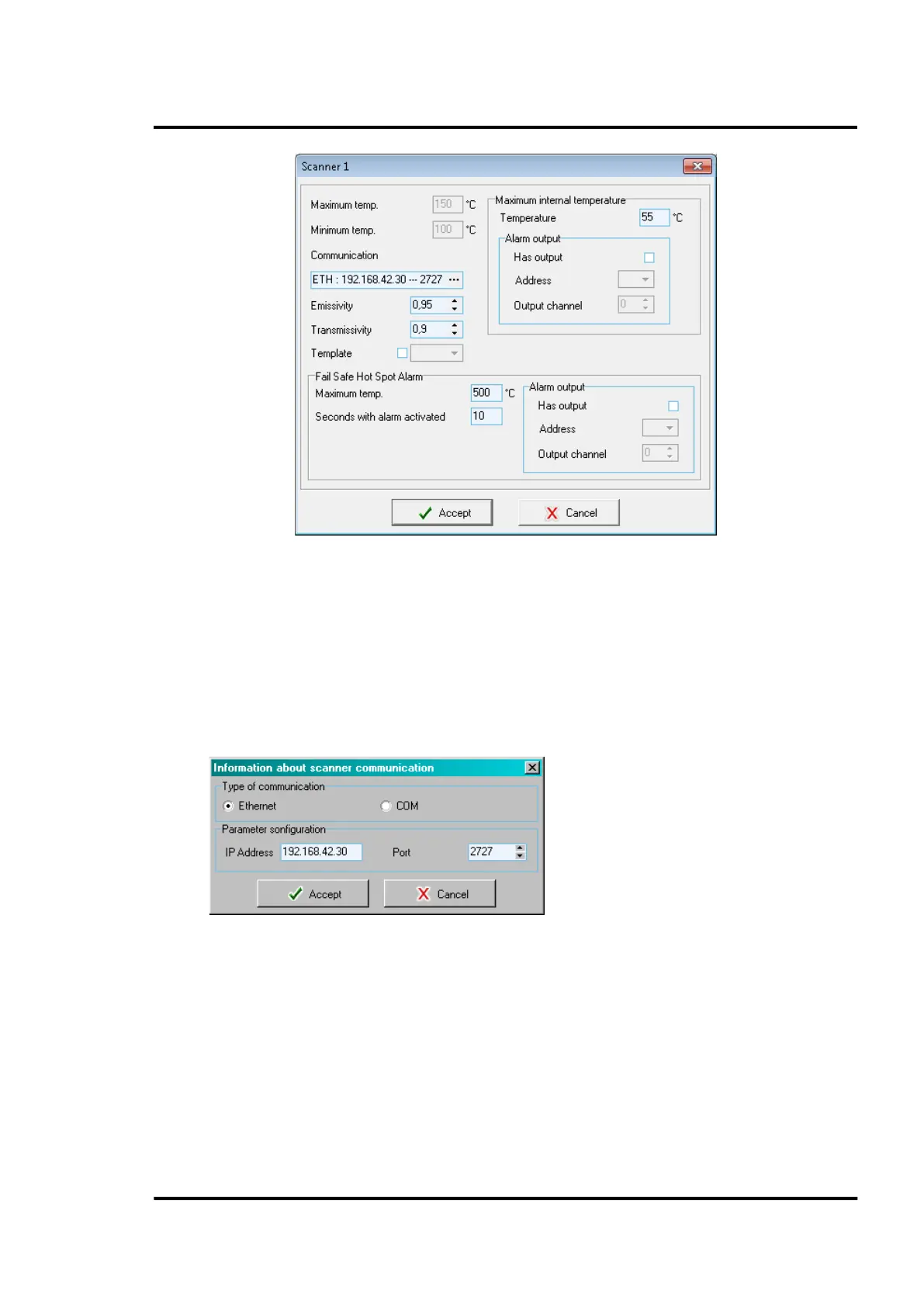
• Communication parameters for the scanner:
Ethernet: <IP Address> for the scanner (default: 192.168.42.30 for the first scanner;
192.168.42.31 for a second scanner, and so on) and <Port> (default: 2727)
For further information to configure the Ethernet communication for scanner and PC network
adapter, see MP150 manual. Please note that all scanners in a multiple scanner system require
a different IP address!
COM: Port number and baud rate
Figure 26: Parameter for the Scanner Communication
• The execution of a template already defined in section 6.2.5 <Special Commands>, page 38.
This template contains scanner commands being executed when ReadScan is initialized.
• The triggering of the scanner <Fail Safe Hot Spot Alarm>. To increase the reliability of the
system it is necessary to guarantee fail-safe hot spot alarming even in the event of a PC or
software crash. For that reason the scanner provides an internal relay that will generate an
alarm if a hot spot that exceeds user-defined limits is detected within the 90° scanner field of
view. The relay contacts are available on the terminal line in the system connection box, see
Figure 8 Connection to the internal Alarm Relay , on page 21.