IMAGE TRANSFER AND PAPER SEPARATION
B039/B040/B043 6-58 SM
6.12.2 IMAGE TRANSFER CURRENT TIMING
There are two transfer current levels: low and high. The image transfer procedure
is as follows:
1. When the CPU receives the image writing start signal, the CPU instructs the
high voltage supply board to supply +10µA (low transfer current level) to the
roller. This prevents any positively charged toner on the drum surface from
transferring to the transfer roller.
2. At a certain time after the low transfer current has been supplied to the roller,
high transfer current is applied to the roller to transfer the toner to the paper
(see the table below).
3. After the trailing edge of the paper has passed through the roller, transfer
current turns off. In multiple copy mode, the transfer current shifts again to the
low transfer current.
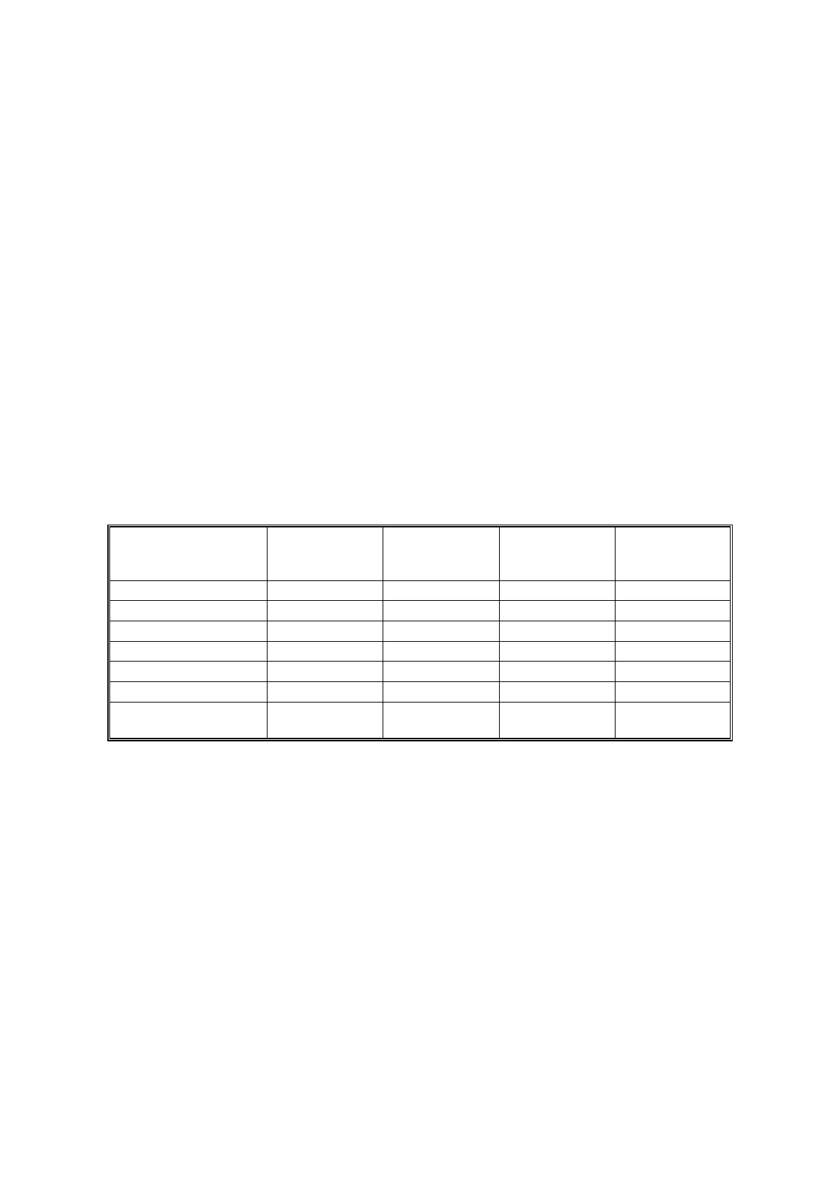
The high transfer current levels (default) are as shown in the following table. With
SP2-301, the high transfer current level used for the paper feed trays, duplex tray,
by-pass tray, and cleaning an be adjusted.
Paper Size
Paper Tray/
By-pass Tray
(Normal)
By-pass Tray
(Thick/OHP)
By-pass Tray
(Special/
Envelope)
Duplex
(2nd Side)
A3/A4 LEF
11 µA 10 µA 12 µA9 µA
11" x 17"
16 µA 11 µA 13 µA 11 µA
B4/B5 LEF
11 µA 11 µA 13 µA 16 µA
8
1/2
" x 11"
15 µA 15 µA 13 µA 17 µA
A4 SEF
13 µA 19 µA 25 µA 19 µA
B5 SEF
17 µA 20 µA 25 µA 20 µA
A5/A6/B6/5
1/2
" x 8
1/2
"
SEF
17 µA 20 µA 25 µA 25 µA
Be careful when increasing the transfer current. This may cause a ghosting effect,
in which part of the image at the top of the page is repeated lower down the page
at a lower density. In the worst case, it may also damage the OPC drum.