Replacement
Adjustment
LASER UNIT
SM 3-21 B039/B040/B043
3.5.6 LASER UNIT ALIGNMENT ADJUSTMENT
!
WARNING
Be absolutely sure to reinstall the copy exit tray before making printouts.
The laser beam can seriously damage your eyes.
1. Use SP5-902 to output a trim pattern (pattern 10). If the pattern is not even,
adjust the alignment as follows.
2. Copy tray (☛ 3.3.3)
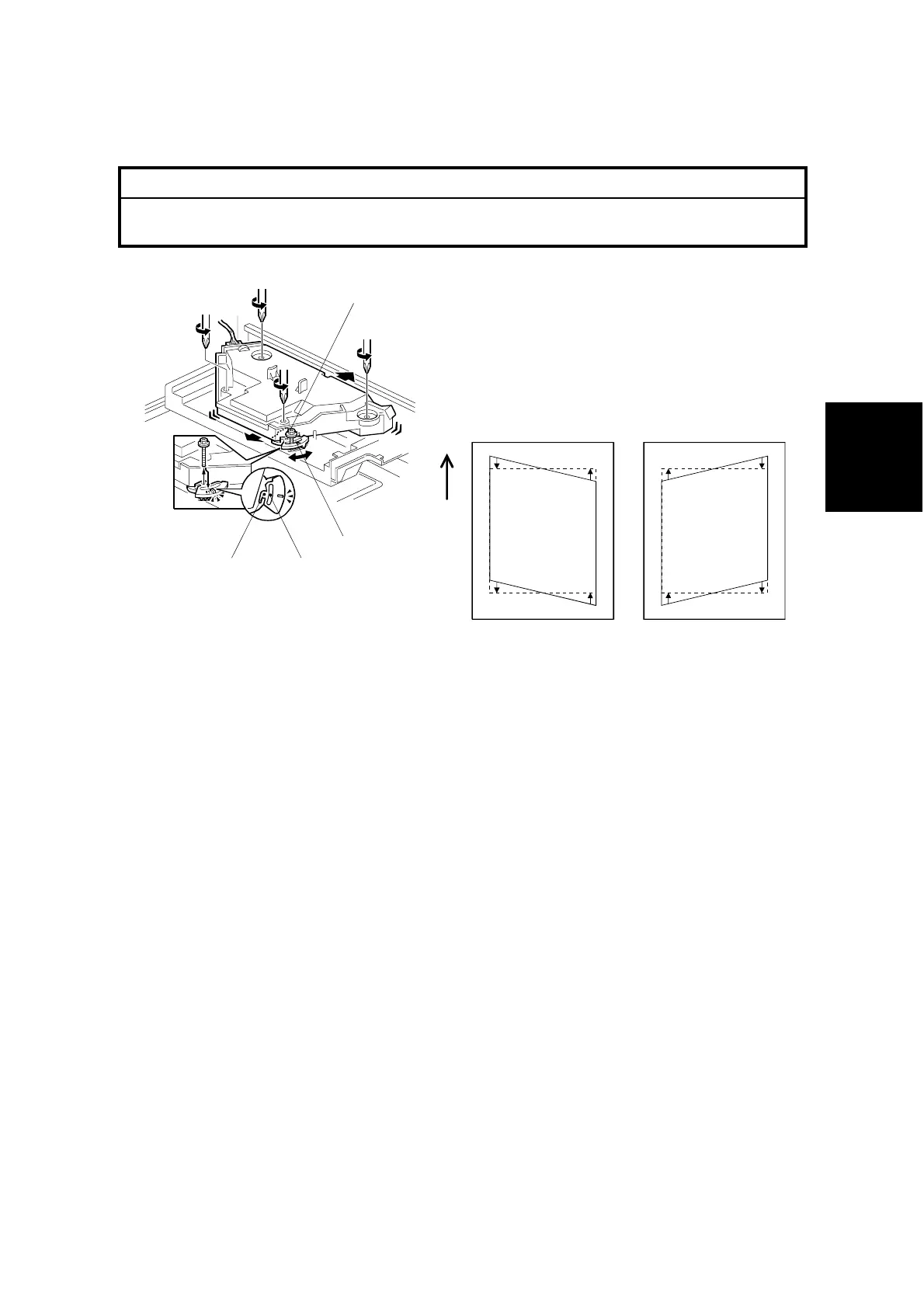
3. Loosen the four screws securing the laser unit (☛ 3.5.3).
4. If this is the first time this adjustment is being made: Remove the adjustment-
lever screw [A] (securing the adjustment lever [B]) from its factory set position
at [C], and loosely screw it in at the center of the long hole [D].
NOTE: If you have already adjusted the alignment at least once, the screw will
already be in the long hole. If readjustment is necessary, just loosen
the screw and continue as follows.
5. Rotate the lever clockwise or counterclockwise. This allows you to shift the
corners of the pattern ±0.4 mm with respect to the leading and trailing edges of
the paper. Using trial and error, adjust until the trim pattern is even.
6. Tighten screw [A] at its new position.
7. Tighten the other three screws.
8. Reinstall the copy tray.
9. Print the trim pattern and check the result. If further adjustment is required,
repeat this procedure.
B039R156.WMF
B039R890.WMF
Turning the lever
counter-clockwise
alters the trim pattern
as shown above
Turning clockwise
alters the trim pattern
as shown above
[A]
[B]
[D][C]