Fax Unit B404
BIT SWITCHES
SM 5-43 B404
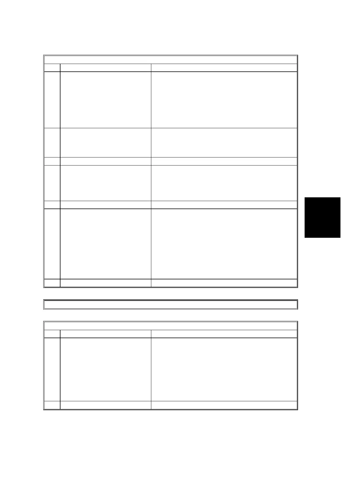
G3 Switch 0A
No FUNCTION COMMENTS
0
1
Maximum allowable carrier
drop during image data
reception
Bit 1 Bit 0 Value (ms)
0 0 200
0 1 400
1 0 800
11Not used
These bits set the acceptable modem carrier drop
time.
Try using a longer setting if error code 0-22 is
frequent.
2
Reception carrier drop
operation.
0: Continue reception
1: Disconnect the line
This bit decides what the machine does when there
is a carrier drop in the image data.
3 Not used Do not change the setting.
4 Maximum allowable frame
interval during image data
reception.
0: 5 s 1: 13 s
This bit set the maximum interval between EOL
(end-of-line) signals and the maximum interval
between ECM frames from the other end.
Try using a longer setting if error code 0-21 is
frequent.
5 Not used Do not change the setting.
6 Reconstruction time for the first
line in receive mode
0: 6 s 1: 12 s
When the sending terminal is controlled by a
computer, there may be a delay in receiving page
data after the local machine accepts set-up data and
sends CFR. This is outside the T.30
recommendation. But, if this delay occurs, set this
bit to 1 to give the sending machine more time to
send data.
Refer to error code 0-20.
ITU-T T.30 recommendation: The first line should
come within 5 s of CFR.
7 Not used Do not change the setting.
G3 Switch 0B - Not used (do not change the settings)
G3 Switch 0C
No FUNCTION COMMENTS
0
1
Pulse dialing method
Bit 1 Bit 0 Setting
00Normal
(P=N)
01Oslo
(P=10 - N)
1 0 Sweden
(N+1)
11Not used
P = Number of pulses sent out, N = Number dialed.
2-7 Not used Do not change the settings.