EasyManuals Logo

SBC PCD1 Series User Manual

SBC PCD1 Series
288 pages
To Next Page IconTo Next Page
To Previous Page IconTo Previous Page
Page #194 background imageLoading...
Page #194 background image
Saia-Burgess Controls AG
Manual Manual PCD 1 / PCD 2 Series │ Document 26 / 737 EN22 │ 2013-11-26
5
Input/output (I/O) modules
5-58
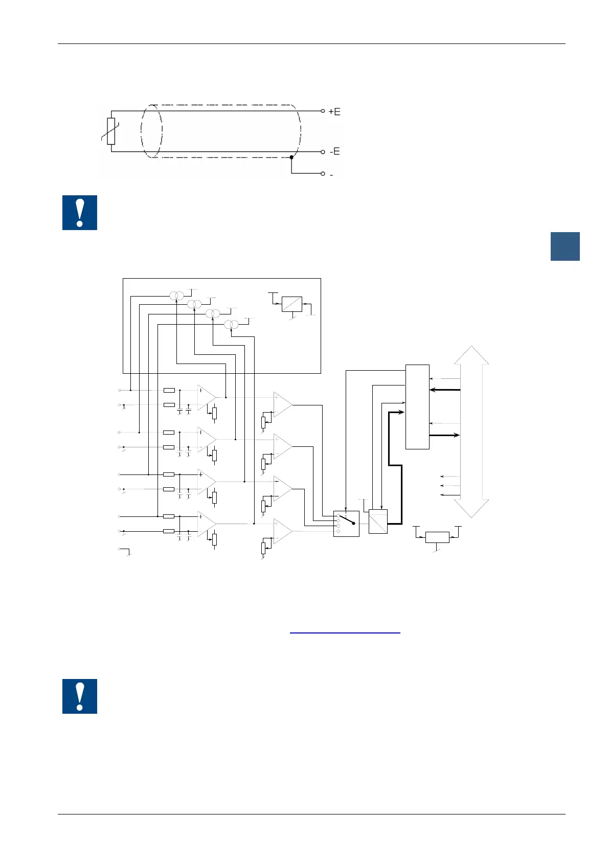
Analogue input modules
Wiring
All unused inputs must be short-circuited: +I to -I in each case
Output circuits and terminal designation
E/A-Bus
DATA
READ
WRITE
PCD - Bus
+5 V
GND
+24 V
DATA
CHANNEL SELECTION
START CONVERSION
A
D
12 BITS
BUSY FLAG
+E0
-E0
9
V+
+15 V
MUX
Gain 3
Offset 0
Offset 1
Offset 2
Offset 3
V
REF
0
1
+E1
2
-E1
3
+E2
4
-E2
5
+E3
6
-E3
7
PGND
Gain 0
V
REF
V
REF
V
REF
V
REF
Icc 0
Icc 1
Icc 2
Icc 3
LINEARISATION
DC
DC
+15 V
-15 V
Gain 1
Gain 2
Programming
Classic: Programming examples for the PCD2.W11x can be found in a separate
manual and on the TCS Support site (www.sbc-support.com + getting started).
xx7: the rmware reads in the values according to the conguration (I/O Builder)
Watchdog: This module can be used on all base addresses; there is no interaction with the
watchdog on the CPUs. For details, please refer to the “Watchdog” section, which describes
the correct use of the watchdog in conjunction with PCD2 components.

Table of Contents

Questions and Answers:

Question and Answer IconNeed help?

Do you have a question about the SBC PCD1 Series and is the answer not in the manual?

SBC PCD1 Series Specifications

General IconGeneral
BrandSBC
ModelPCD1 Series
CategoryController
LanguageEnglish

Related product manuals