Saia-Burgess Controls AG
Manual Manual PCD 1 / PCD 2 Series │ Document 26 / 737 EN22 │ 2013-11-26
5
Input/output (I/O) modules
5-57
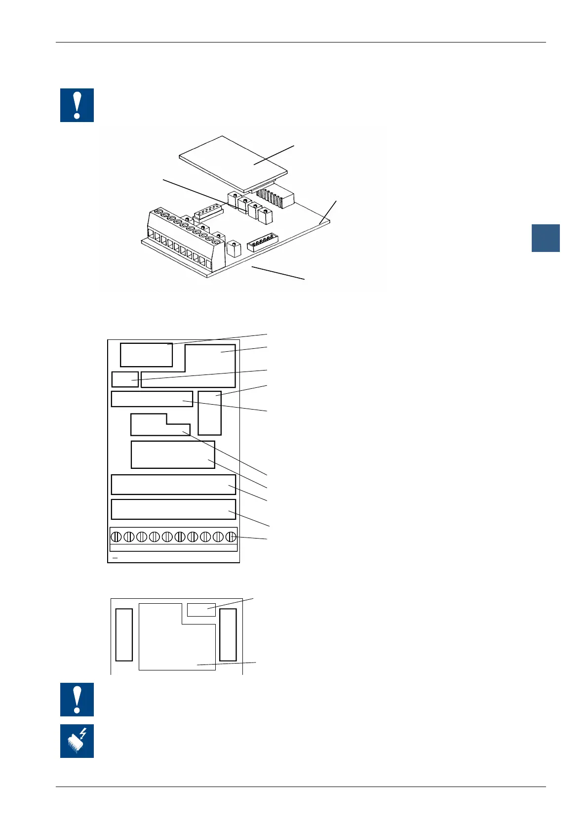
Analogue input modules
The 4 built-in potentiometers for setting the amplication are not accessible to the
user and must not be adjusted.
Not user
accessible
Substitution module
Basic module
Adjustment
of offset
Terminals
Basic module
Bus connector
I/O bus interface
+15 V
A/D converter
Adjustment of amplification
(not for users)
Digital value = 4095
Temperature = +150°C
Analogue multiplexer
Input amplifier
Adjustment of offset
Digital value = 0 --> Temperature = –50°C
Input filter
Screw terminals
9 8 7 6 5 4 3 2 1 0
-E0+-E1+-E2+-E3+
-15V
Current sources and
linearization
J1 J2
Input 1 Input 0Input 2Input3
Ground
The negative terminals for each input are connected to the ground.
On this circuit board there are components that are sensitive to electrostatic
discharges. For further information, refer to Appendix B, “Icons”.