Saia-Burgess Controls AG
Manual Manual PCD 1 / PCD 2 Series │ Document 26 / 737 EN22 │ 2013-11-26
5
Input/output (I/O) modules
5-56
Analogue input modules
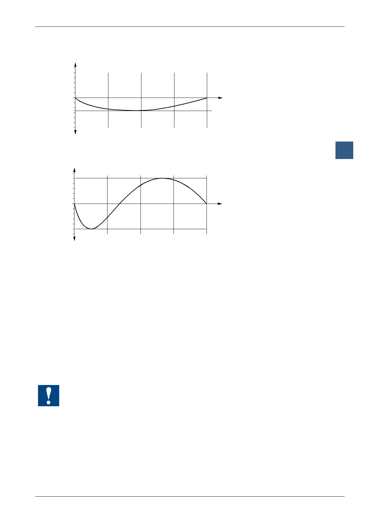
Typical linearity error for W110/112/114 (Pt 100/Pt 1000)
-50
0
0
1024
+50
2047.5
+100
3071
+150
4095
°C
LSB
Measurement
Deviation (LSB)
0
+1
+2
+3
+4
+5
+1
+2
+3
+4
+5
+6
+6
Typical linearity error for W111/113 (Ni 100/Ni 1000)
-50
0
0
1024
+50
2047.5
+100
3071
+150
4095
°C
LSB
Measurement
Deviation (LSB)
0
+1
+2
+3
+4
+5
+1
+2
+3
+4
+5
+6
+6
On cable break → Measurement 4095
On short circuit → Measurement 0
Base and variant modules
Each module comprises 2 individual modules.
● Base module with input lters, A/D converter, I/O port. Same module with same
ttings for all 4 variants.
● Plug-on variant modules with switching circuit to generate -15 V, power sources
and linearization. Each of the four variants has a module of its own, i.e. a
module with different equipment.
The user has access to the 4 potentiometers to set the offset for each individual
channel. This can be useful for adjusting the zero value (at -50 °C) for long
measurement cables.
All modules are set up in pairs (base and variant module) at the factory. The variant
modules must not be exchanged.