Saia-Burgess Controls AG
Manual Manual PCD 1 / PCD 2 Series │ Document 26 / 737 EN22 │ 2013-11-26
5
Input/output (I/O) modules
5-67
Analogue input modules
Digital/analogue values
Input signals and type Digital values
PCD2.W300/W340 PCD2.W310/W340 PCD2.W340/50/60 Classic xx7 Simatic
+ 10.0 V + 20 mA
Calculate the appro-
priate values with the
formulae at the end
of this section
4095 4095 27684
+ 5.0 V + 10 mA 2047 2047 13824
0 V 0 mA 0 0 0
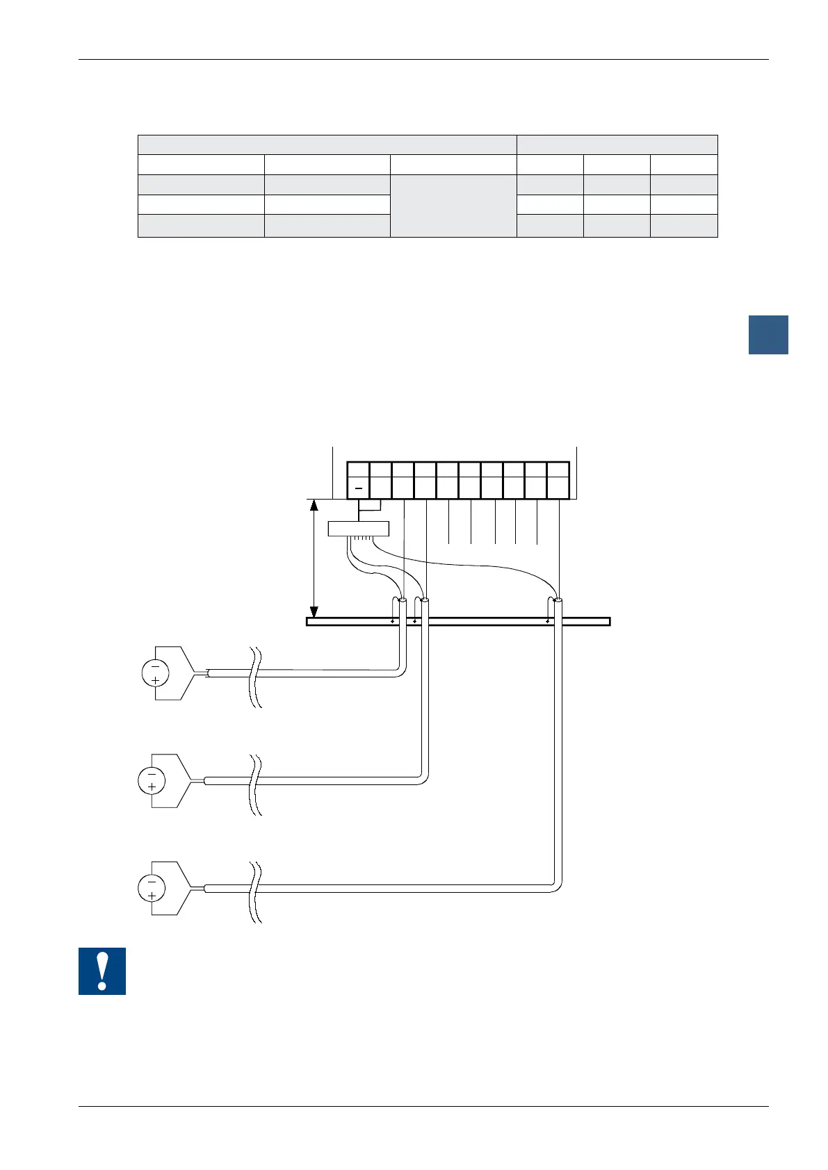
Connection concept for voltage and current inputs
The voltage and current input signals are connected directly to the 10-pole terminal
block (E0 … E7). To minimize the amount of interference coupled into the module
via the transmission lines, connection should be made according to the principle
explained below.
The following connection diagram shows a typical wiring layout for:
● voltage inputs with the PCD2.W300 and … W340 Modules or
● current inputs with the PCD2.W310 and … W340 Modules
89
E6
67
E4
45
E1
23
E0
01
E3 E2E5E7
Earthing bar
max. 20cm
COM
Distributor *)
● The reference potentials of signal sources should be wired to a common GND
connection (“–” and “COM” terminals). To obtain optimum measurement results,
any connection to an earthing bar should be avoided
● If shielded cables are used, the shield should be continued to an external earthing
bar.