Saia-Burgess Controls AG
Manual Manual PCD 1 / PCD 2 Series │ Document 26 / 737 EN22 │ 2013-11-26
5
Input/output (I/O) modules
5-68
Analogue input modules
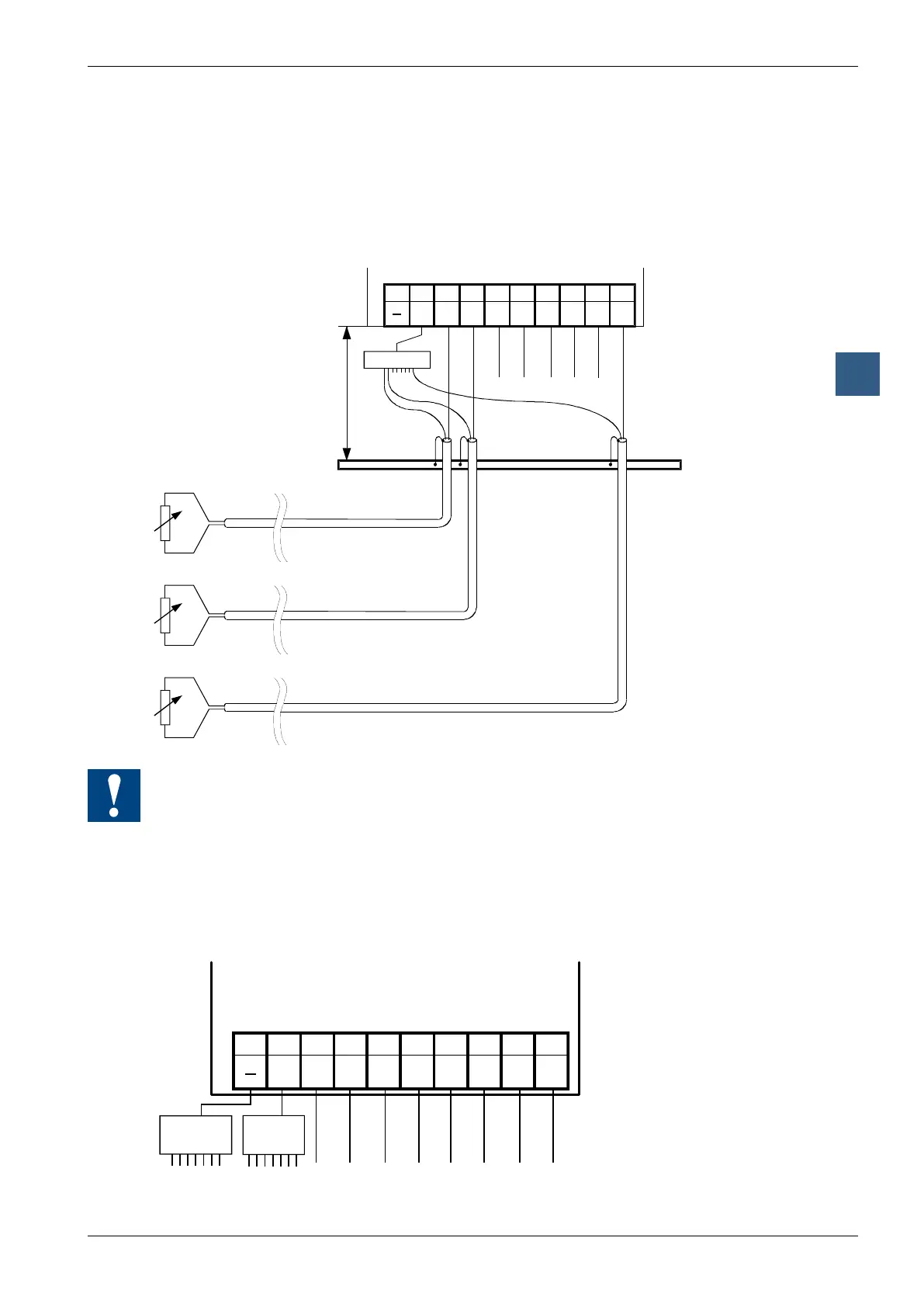
Connection concept for temperature sensors
The input signals for the temperature sensors are connected directly to the 10-pole
terminal block (E0 … E7).
The following connection diagram shows a typical layout for tempera-
ture sensors with the PCD2.W340, … W350 and … W360 Modules.
E6
E4
E1
E0
E3 E2E5E7
Earthing bar
COM
Distributor *)
*) potential free
● The reference potential for temperature measurements is the “COM” terminal,
which should not have any external earth or GND connection.
● If screened cables are used, screening should be continued to an external
earthing bar.
● Unused temperature inputs are to be connected to the logical ground.
Mixed operation
89
E6
67
E4
4 5
E1
2 3
E0
0 1
E3 E2E5E7
COM
Distributor
‘V’ and ‘C’
Distributor
Temp.