Saia-Burgess Controls AG
Manual Manual PCD 1 / PCD 2 Series │ Document 26 / 737 EN22 │ 2013-11-26
5
Input/output (I/O) modules
5-69
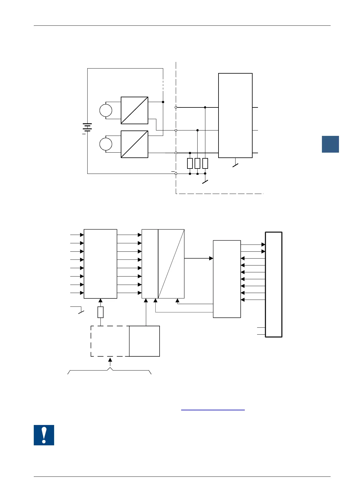
Analogue input modules
Connection concept for two-wire transducers
E1
E0
GND
PCD2.W310/340
0...20 mA
4...20 mA*
ρ
ϑ
24 VDC
Pressure
Tempera-
ture
Input filter
+
E2
*4...20 mA over user program
Two-wire transducers need a 24 VDC-supply in the measuring trunk.
Block diagram
Voltage
Source
10.000V
Ref.
Voltage
2.500V
Input filter
and amplifier
Programming
Classic:
Programming examples for the PCD2.W3x0 can be found in a separate man-
ual and on the TCS Support site (www.sbc-support.com + getting started).
xx7: the rmware reads in the values according to the conguration (I/O Builder)
Watchdog: This module cannot be used on the base address 240 (or 496 for the
PCD2.M17x), because it would interact with the watchdog, and would cause a
malfunction.
For details, please refer to the “Watchdog” section, which describes the correct use of
the watchdog in conjunction with PCD2 components.