Saia-Burgess Controls AG
Manual Manual PCD 1 / PCD 2 Series │ Document 26 / 737 EN22 │ 2013-11-26
5
Input/output (I/O) modules
5-83
Analogue output modules
Changing the jumpers
There are components on this circuit board, that are sensitive to electrostatic discharges.
For further information, refer to Appendix B, “Icons”.
Range selection (PCD2.W610)
Jumpers, factory settings: A0 … A3: “V” (voltage)
U/B: “B” (bipolar)
Reset select: “mid“ (reset to mid-scale,
i.e. 0 V in bipolar mode)
Ranges depending on application:
Per module: U/B: Unipolar or Bipolar operation
Reset select: Reset to low- or mid-scale
Rec. setting: Unipolar →low-scale
Bipolar → mid-scale
Per channel: “V” Voltage output:
0 … +10 V or -10 V … +10 V
“C”: Current output: 0 … 20 mA
Current outputs have been laid out for unipolar mode. Bipolar mode is possible, but
for the negative half of this operation the output is 0 mA.
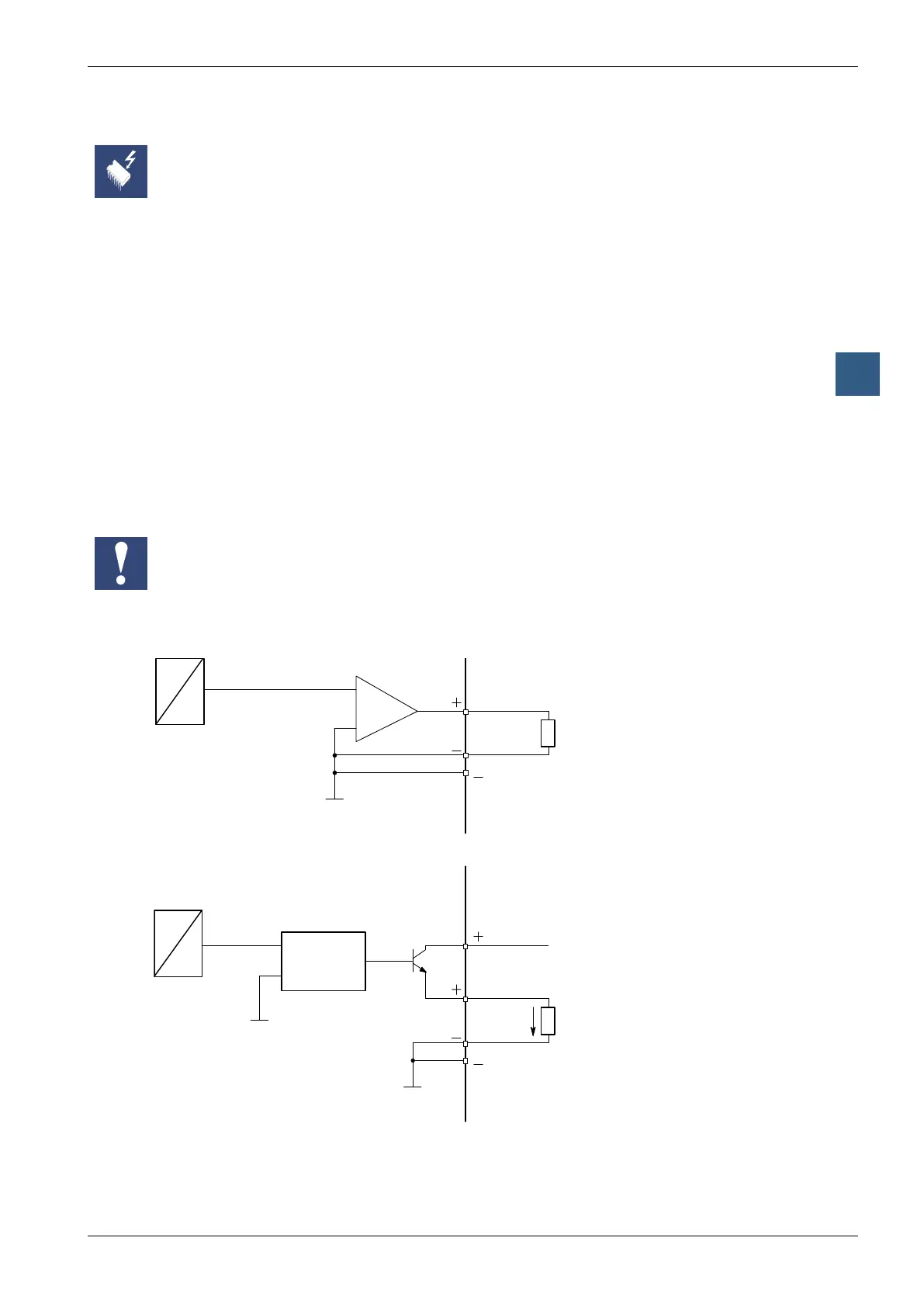
Connection concept
Connection for 0 … 10 V or -10 V … +10 V: (selectable on the PCD2.W610)
4 (A2)
Connection for 0 … 20 mA: (PCD2.W610 only)
4 (A2)
Contrôle de la
tension de la
source de
courant
An external 24 VDC supply is required for current outputs.