Saia-Burgess Controls AG
Manual Manual PCD 1 / PCD 2 Series │ Document 26 / 737 EN22 │ 2013-11-26
5
Input/output (I/O) modules
5-87
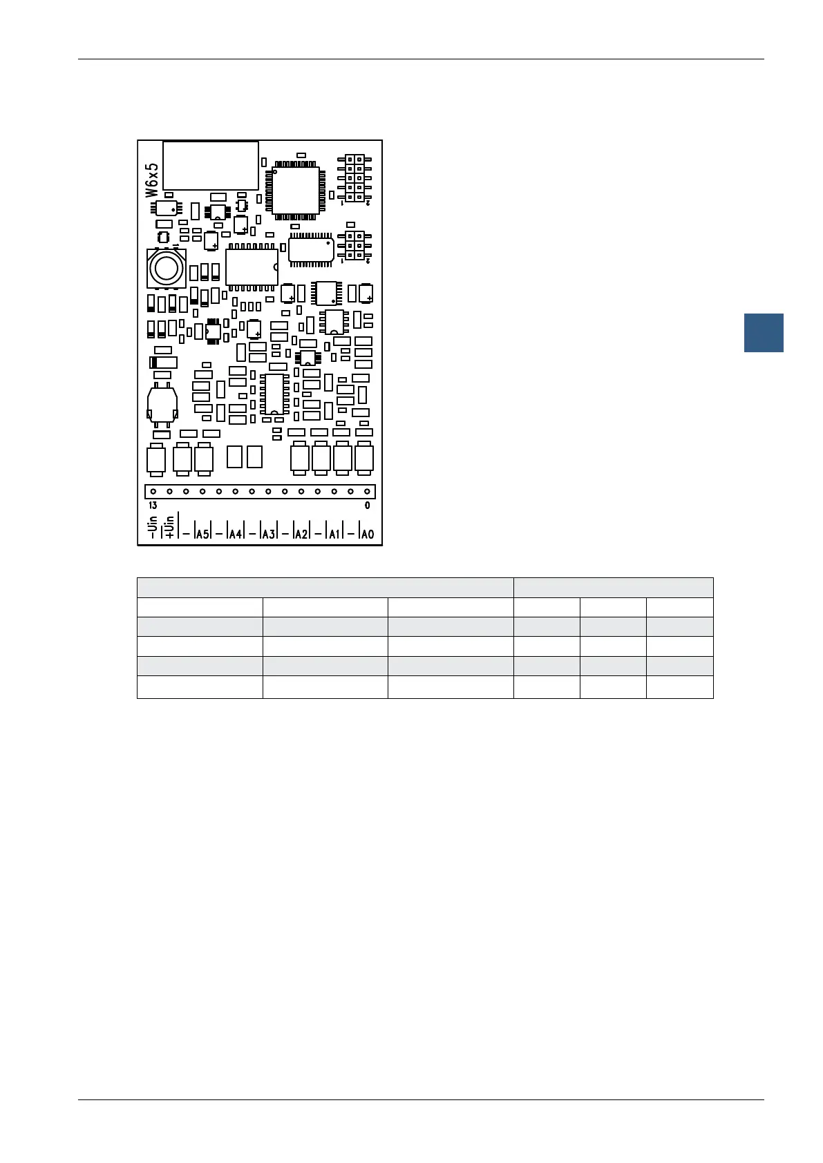
Analogue output modules with electrically isolation
Terminals
Digital/analogue values
Output signals and type Digital values
PCD2.W605 PCD2.W615 PCD2.W625 Classic xx7 Simatic
+ 10.0 V + 20 mA
+10 V
1023 1023 27684
+ 5.0 V + 10 mA
0 V
512 512 13842
+ 4 mA 205 205 5530
0 V 0 mA
-10 V
0 0 0
Notes on the output range
Balancing the offset and the amplication is done for the PCD2.W6x5 digitally by the
µC. As there is no potentiometer, the output range has been slightly enlarged to cover
maximum values even in the worst case.
Typical output range (without component tolerances):
W605: - 0.26 V … + 10.36 V (instead of 0 … + 10 V)
W615: 0 mA … 21.4 mA (instead of 0 … 20 mA)
W625: - 10.62 V … 10.36 V (instead of - 10 … +10 V)
This range is broken down on a 10 bit scale (1024 steps), as before. The result is the
following LSB resolution:
W605: 1 LSB = 10.38 µV
W615: 1 LSB = 21.7 µA
W625: 1 LSB = 20.75 µV
With this balance the nominal range (0 … 10 V) is now scaled 0 … 1023, making it
possible for the output value not to change on an increase of 1 LSB.